Configuration considerations, Configuration procedure – H3C Technologies H3C S12500 Series Switches User Manual
Page 31
17
on GigabitEthernet 3/0/3 and GigabitEthernet 3/0/1. Enable proxy ARP on Switch A to allow
communication between Host A and Host B.
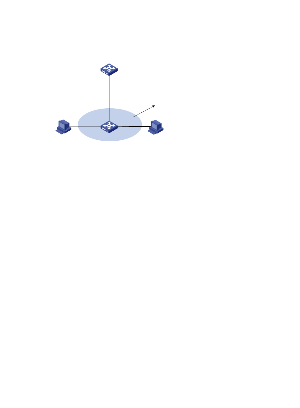
Figure 8 Network diagram
Configuration considerations
In this configuration example, suppose all traffic between the hosts is blocked, so you need to configure
local proxy ARP on VLAN-interface 2 of Switch A to enable communication between Host A and Host B.
If the two ports (GigabitEthernet 3/0/3 and GigabitEthernet 3/0/1) on Switch B are isolated only at
Layer 2, you can enable communication between the two hosts by configuring local proxy ARP directly
on VLAN-interface 2 of Switch B.
Configuration procedure
1.
Configure Switch B:
# Add GigabitEthernet 3/0/3, GigabitEthernet 3/0/1, and GigabitEthernet 3/0/2 to VLAN 2.
Host A and Host B are isolated and unable to exchange Layer 2 packets.
<SwitchB> system-view
[SwitchB] port-isolate group 2
[SwitchB] vlan 2
[SwitchB-vlan2] port gigabitethernet 3/0/3
[SwitchB-vlan2] port gigabitethernet 3/0/1
[SwitchB-vlan2] port gigabitethernet 3/0/2
[SwitchB-vlan2] quit
[SwitchB] interface gigabitethernet 3/0/3
[SwitchB-GigabitEthernet3/0/3] port-isolate enable group 2
[SwitchB-GigabitEthernet3/0/3] interface gigabitethernet 3/0/1
[SwitchB-GigabitEthernet3/0/1] port-isolate enable group 2
[SwitchB-GigabitEthernet3/0/1] interface gigabitethernet 3/0/2
[SwitchB-GigabitEthernet3/0/2] port-isolate uplink-port group 2
2.
Configure Switch A:
# Create VLAN 2, and add GigabitEthernet 3/0/2 to VLAN 2.
<SwitchA> system-view
[SwitchA] vlan 2
[SwitchA-vlan2] port gigabitethernet 3/0/2
[SwitchA-vlan2] quit
GE3/0/2
VLAN 2
Vlan-int2
192.168.10.100/16
Switch B
GE3/0/3
GE3/0/1
GE3/0/2
uplink-port
Host A
192.168.10.99/16
Host B
192.168.10.200/16
VLAN 2
port-isolate group 2
Switch A