User login control – H3C Technologies H3C S12500-X Series Switches User Manual
Page 159
147
[SwitchA] display ipsec sa
-------------------------------
Interface: Vlan-interface 1
-------------------------------
-----------------------------
IPsec policy: map1
Sequence number: 10
Mode: manual
-----------------------------
Tunnel id: 549
Encapsulation mode: tunnel
Path MTU: 1443
Tunnel:
local address: 2.2.2.1
remote address: 2.2.3.1
Flow:
as defined in ACL 3101
[Inbound ESP SA]
SPI: 54321 (0x0000d431)
Transform set: ESP-ENCRYPT-AES-CBC-192 ESP-AUTH-SHA1
No duration limit for this SA
[Outbound ESP SA]
SPI: 12345 (0x00003039)
Transform set: ESP-ENCRYPT-AES-CBC-192 ESP-AUTH-SHA1
No duration limit for this SA
250B
Configuring an IKE-based IPsec tunnel for IPv4 packets
474B
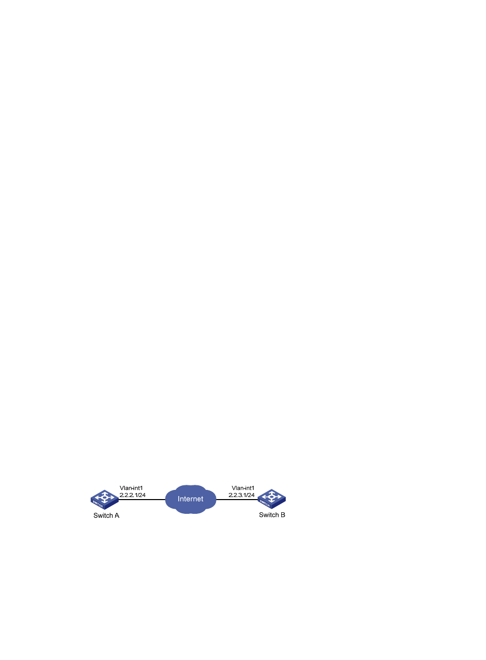
Network requirements
As shown in
857H
Figure 44
, establish an IPsec tunnel between Switch A and Switch B to protect data flows
between the switches. Configure the IPsec tunnel as follows:
•
Specify the encapsulation mode as tunnel, the security protocol as ESP, the encryption algorithm as
AES-CBC-192, and the authentication algorithm as HMAC-SHA1.
•
Set up SAs through IKE negotiation.
Figure 44 Network diagram
475B
Configuration procedure
1.
Configure Switch A:
# Configure an IP address for VLAN-interface 1.
<SwitchA> system-view
[SwitchA] interface vlan-interface 1