Verifying the configuration, Configuration example (on a dhcp server) – H3C Technologies H3C S12500-X Series Switches User Manual
Page 235
223
Step Command
Remarks
1.
Enter system view.
system-view
N/A
2.
Enter Layer 3 Ethernet interface
view.
interface interface-type
interface-number
N/A
3.
Enable authorized ARP on the
interface.
arp authorized enable
By default, authorized ARP is
disabled.
308B
Configuration example (on a DHCP server)
532B
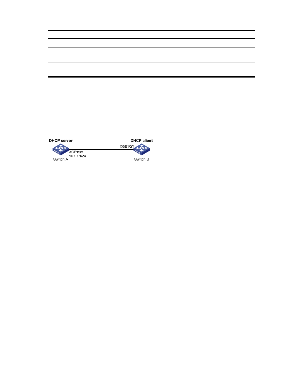
Network requirements
Configure authorized ARP on Ten-GigabitEthernet 1/0/1 of Switch A (a DHCP server) to ensure user
validity.
Figure 70 Network diagram
533B
Configuration procedure
1.
Configure Switch A:
# Specify the IP address for Ten-GigabitEthernet 1/0/1.
<SwitchA> system-view
[SwitchA] interface ten-gigabitethernet 1/0/1
[SwitchA-Ten-GigabitEthernet1/0/1] ip address 10.1.1.1 24
[SwitchA-Ten-GigabitEthernet1/0/1] quit
# Configure DHCP.
[SwitchA] dhcp enable
[SwitchA] dhcp server ip-pool 1
[SwitchA-dhcp-pool-1] network 10.1.1.0 mask 255.255.255.0
[SwitchA-dhcp-pool-1] quit
# Enter Layer 3 Ethernet interface view.
[SwitchA] interface ten-gigabitethernet 1/0/1
# Enable authorized ARP.
[SwitchA-Ten-GigabitEthernet1/0/1] arp authorized enable
[SwitchA-Ten-GigabitEthernet1/0/1] quit
2.
Configure Switch B:
<SwitchB> system-view
[SwitchB] interface ten-gigabitethernet 1/0/1
[SwitchB-Ten-GigabitEthernet1/0/1] ip address dhcp-alloc
[SwitchB-Ten-GigabitEthernet1/0/1] quit
3.
After Switch B obtains an IP address from Switch A, display the authorized ARP entry information
on Switch A.
[SwitchA] display arp all