Cooling – H3C Technologies H3C S12500-X Series Switches User Manual
Page 13
Advertising
5
Cooling
Plan the installation site for adequate ventilation:
•
Leave a minimum of 30 cm (11.81 in) of clearance at the inlet and outlet air vents.
•
The rack for the switch has a good cooling system.
•
The installation site has a good cooling system.
•
Verify that the airflow design of the chassis meets the airflow design of the installation site.
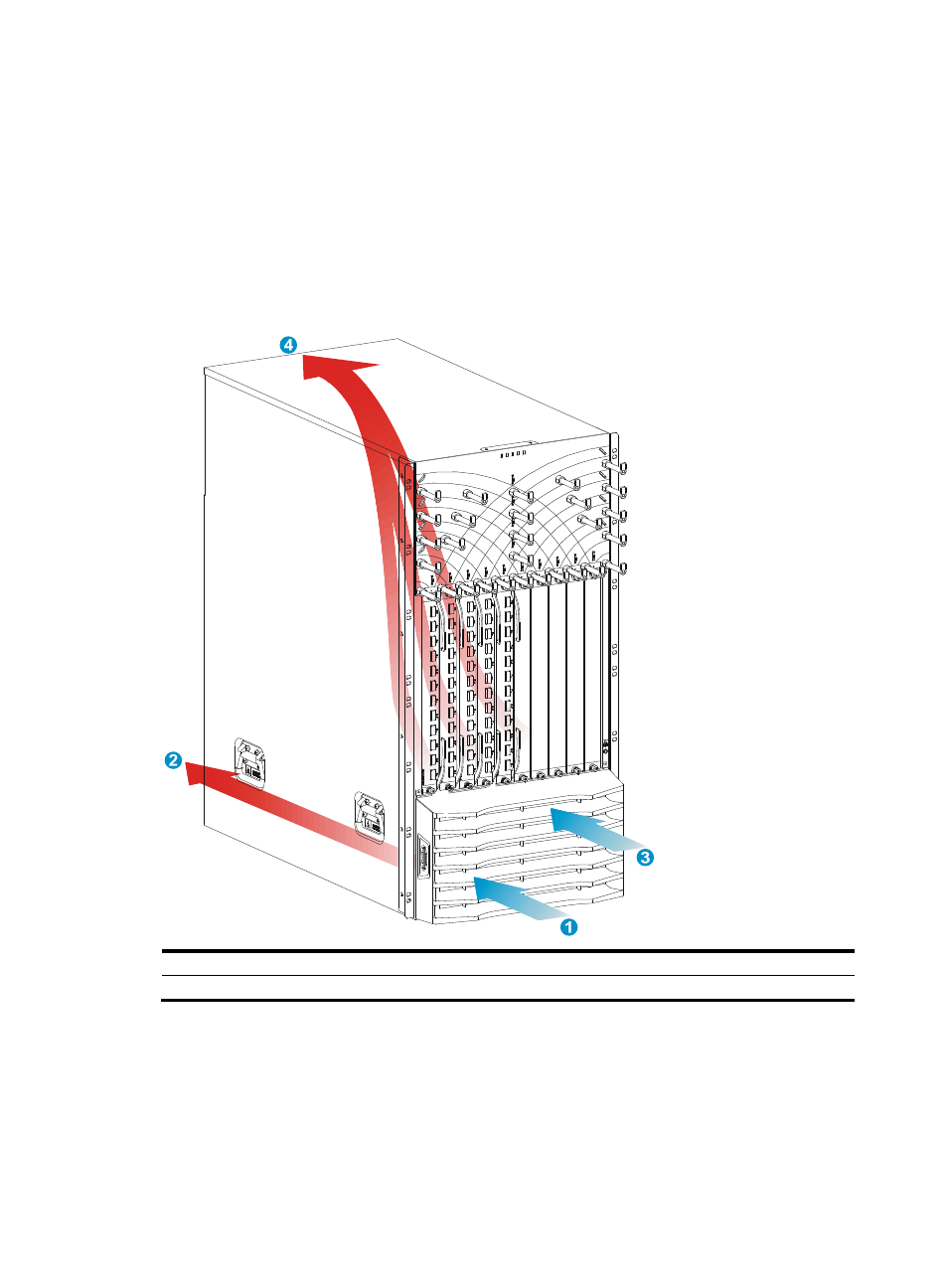
Figure 1 Airflow through the S12510-X AC/S12510-X DC chassis
(1) Power module air inlet vents
(2) Power module air outlet vents
(3) Chassis air inlet vents
(4) Chassis air outlet vents
Advertising