Optional) installing a dc input terminal block – H3C Technologies H3C S12500-X Series Switches User Manual
Page 45
37
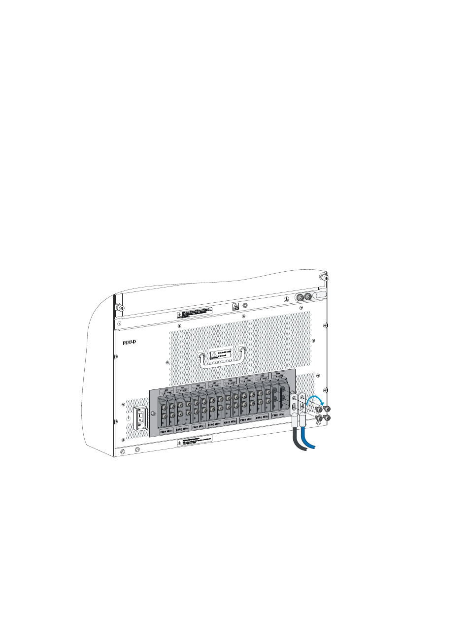
To connect DC power cords:
1.
Loosen the screws on an RTN(+) terminal (PWR1, for example) on the terminal block, and remove
the screws.
2.
As shown in
, use screws to secure the terminal of the black DC power cord to the RTN(+)
terminal.
3.
Use the same method to connect the terminal of the blue DC power cord to the NEG(-) terminal.
4.
Connect the other ends of the DC power cords to the power source and switch on the circuit
breaker.
{
Blue DC power cord—–48V terminal.
{
Black DC power cord—RTN terminal.
5.
Connect all power cords, and turn on the power switch to the left of the power receptacles.
6.
Examine the power module input/output status LEDs.
If all the LEDs are on, the power cords are correctly connected. For description of power module
status LEDs, see "Appendix C LEDs."
7.
Install the plastic panel to the air inlet vents at the lower part of the front panel. For installing the
plastic panel, see "Installing the switch."
Figure 30 Connecting DC power cords
(Optional) Installing a DC input terminal block
For an S12500-X DC switch, if the power distribution box is far away from the rack, you can order an
extension cable and a DC input terminal block to supply power to the device.
A DC input terminal block provides eight pairs of terminals. Each pair uses two wires to provide DC
power supply. A maximum of eight pairs of wires are supported. The terminals support cables with a size
of 10 mm² to 35 mm² (0.02 sq.in to 0.05 sq.in)