H3C Technologies H3C S12500-X Series Switches User Manual
Page 26
18
Sign Meaning Remarks
F/R
Front end of the right slide rail
Mount this end to the front right rack post.
2.
Mark the installation position on the rack posts for the slide rails:
a.
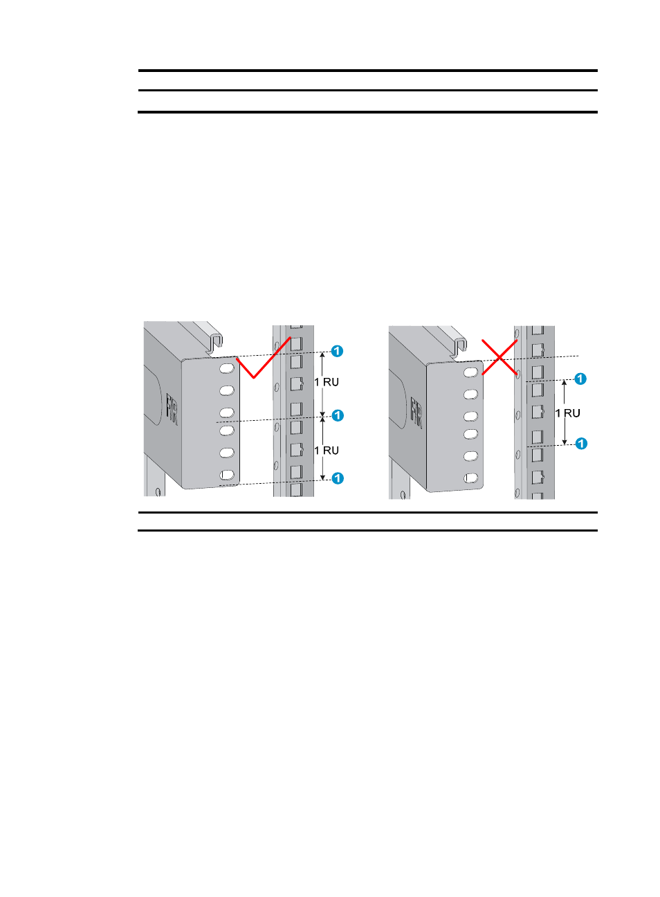
Make sure the top flange of a slide rail aligns with the middle of the narrower metal area
between holes on a rack post, as shown in
.
One rack unit (RU) has three holes, the middle of which is an auxiliary installation hole, and the
other two are standard installation holes. You can distinguish them by the space between each
two holes. The space between a standard installation hole and an auxiliary installation hole is
wider than that between two adjacent standard installation holes.
b.
Each rack post requires six screws to attach the slide rail. Mark the uppermost square hole and
lowermost square hole for installation.
c.
Mark the square holes at the same height on the other three rack posts.
Figure 11 Marking the installation position on the rack for the slide rails
(1) Middle of the narrower metal area between holes
3.
Install six cage nuts in the square holes in each rack post:
a.
Insert the lower ear of a cage nut into the hole, as shown by callout 1 in
.
b.
Compress the upper and lower ears of the cage nut to lead the upper ear through the hole, as
shown by callout 2 in
c.
Repeat steps a and b to install cage nuts in all the square holes in the rack posts.