H3C Technologies H3C SR6600 User Manual
Page 106
Advertising
96
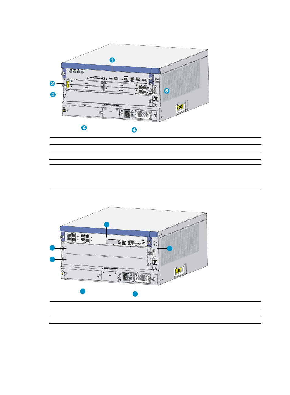
Figure 91 Front view (an RSE-X1 MPU installed)
(1) MPU slot (slot 1)
(2) MPU/service module slot (slot 2)
(3) Service module slot (slot 3)
(4) Power module slots
(5) Fan tray
NOTE:
In this figure, one RSE-X1 MPU is installed. You can install one more RSE-X1 MPU or install one service
module in the MPU/service module slot.
Figure 92 SR6604 front view (an MCP-X1 installed)
(1) MPU slot (slot 1)
(2) MPU/service module slot (slot 2)
(3) Service module slot (slot 3)
(4) Power module slots
(5) Fan tray
1
2
3
4
4
5
Advertising