H3C Technologies H3C SR6600 User Manual
Page 45
35
The 10/100 Mbps Ethernet uses two pairs of cables, orange/white, orange, green/white and green
cables, to transmit and receive data, while the 1000 Mbps Ethernet uses four pairs of cables to transmit
and receive data.
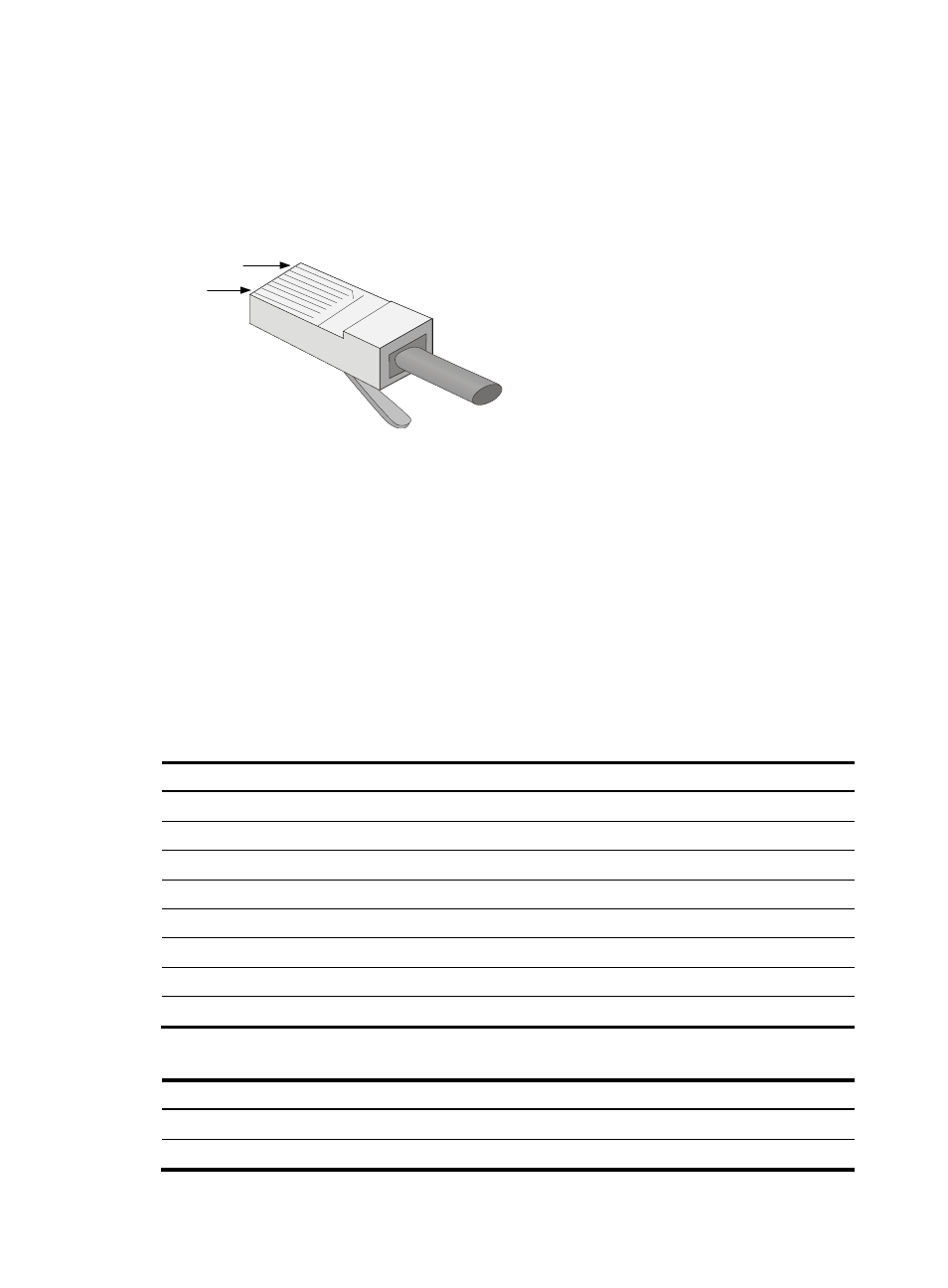
An Ethernet twisted pair cable connects network devices through the RJ-45 connectors at the two
ends.
shows the pinouts of an RJ-45 connector.
Figure 37 RJ-45 connector pinout
EIA/TIA cabling specifications define two standards, 568A and 568B, for cable pinouts.
•
Standard 568A—Pin 1: white/green stripe, pin 2: green solid, pin 3: white/orange stripe, pin 4:
blue solid, pin 5: white/blue stripe, pin 6: orange solid, pin 7: white/brown stripe, pin 8: brown
solid.
•
Standard 568B—Pin 1: white/orange stripe, pin 2: orange solid, pin 3: white/green stripe, pin 4:
blue solid, pin 5: white/blue stripe, pin 6: green solid, pin 7: white/brown stripe, pin 8: brown
solid.
Ethernet twisted pair cables can be classified into straight-through and crossover cables based on their
pinouts.
For the pinouts of the twisted pair cables, see the following tables. (A and B represent the two ends of a
cable, respectively.)
Table 7 Straight-through cable pinouts
Pinout No.
A
B
1 Orange/white Orange/white
2 Orange
Orange
3 Green/white Green/white
4 Blue
Blue
5 Blue/white
Blue/white
6 Green
Green
7 Brown/white Brown/white
8 Brown
Brown
Table 8 Crossover cable pinouts
Pinout No.
A
B
1 Orange/white Green/white
2 Orange
Green
PIN #8
PIN #1