Power on the l10 raid chassis, Preparing k2 storage system clients, Chapter 7 installing the level 10 storage system – Grass Valley K2 Storage System Instruction Manual v.3.2 Sep.24 2007 User Manual
Page 304
304
K2 Storage System Instruction Manual
September 7, 2007
Chapter 7 Installing the Level 10 Storage System
Once the RAID storage is connected and configured, do not swap Expansion chassis
or otherwise reconfigure storage. If you connect an Expansion chassis in a different
order or to the wrong controller, the controller will see a configuration mismatch and
fault.
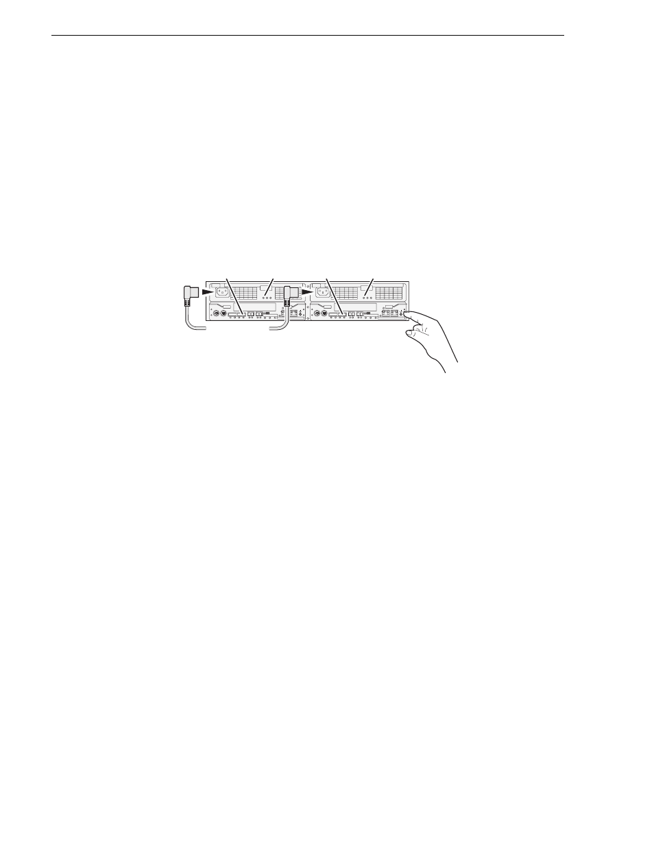
Power on the L10 RAID chassis
Connect power cords and power up RAID storage devices as follows:
1. Verify power and cabling.
2. Press and hold down the power button on the controller, as shown.
If the RAID chassis has two controllers, you can press the power button on either
controller. You do not need to press both power buttons.
Pressing the power button on a controller also powers on any connected Expansion
chassis. There are no power buttons on Expansion chassis.
3. Release the power button when the Power Good LED on the power supply is
illuminated. This takes 1-3 seconds.
4. Wait while the primary RAID chassis performs self-test and initialization. This
takes about four minutes. While this is taking place, the RDY LED is illuminated
with a steady on light.
5. Watch for the RDY LED to begin blinking at one second intervals. The LED might
turn off and back on two times before starting the one second blink pattern. When
the RDY LED is blinking at one second intervals, the self-test and initialization is
complete and the chassis is ready for use.
Your preparations for L10 RAID storage are now complete.
Preparing K2 Storage System clients
Any devices that function as iSCSI clients to the K2 Storage System must be prepared
with the following requirements:
• One or more connections to the control network.
• A static IP address for the control network.
• For a non-redundant K2 Storage System, one connection to the media (iSCSI)
network.
Additional steps that are required for Aurora Edits include the following:
BBU IN
MODEM
FLT/LNK
HPE
FLT
A/L
BACKUP
ACT/LNK
LNK/ACT
FLT
HP
5 4 3 2
RDY
LAN
BAT
MNT
ACS
MC
DP1
DP0
HP
1 0
BBU IN
MODEM
FLT/LNK
HPE
FLT
A/L
BACKUP
ACT/LNK
LNK/ACT
FLT
HP
5 4 3 2
RDY
LAN
BAT
MNT
ACS
MC
DP1
DP0
HP
1 0
Power Cords
(115V/2
3
0V)
RDY
LED
RDY
LED
Power Good
LED
Power Good
LED