Adjusting input video, Assigning video buses to output connectors, About audio outputs assigned to video buses – Roland V-160HD SDI/HDMI Streaming Video Switcher User Manual
Page 14: Video input/output settings
14
Video Input/Output Settings
Adjusting Input Video
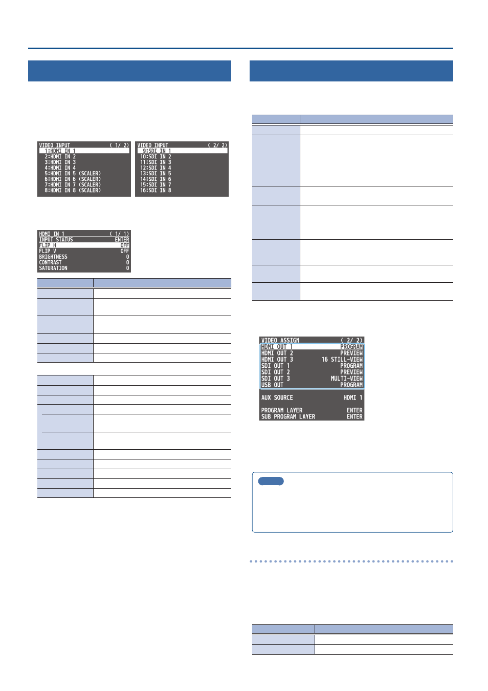
Here’s how to adjust the quality of the input video signals.
For the HDMI IN 5–8 connectors, you can also adjust the scaling.
1 .
[MENU] button
Ó
“VIDEO INPUT”
Ó
select “HDMI IN 1–
8 (SCALER)” or “SDI IN 1–8,” and press the [VALUE] knob.
2 .
Use the [VALUE] knob to select a menu item shown below,
and press the [VALUE] knob.
Menu item
Explanation
INPUT STATUS
Displays information about the incoming video.
FLIP H
When this is “ON,” the video is input with left and
right flipped.
FLIP V
When this is “ON,” the video is input with top and
bottom flipped.
BRIGHTNESS
Adjusts the brightness.
CONTRAST
Adjusts the contrast.
SATURATION
Adjusts the saturation.
* The following parameters are only for HDMI IN 5–8 (SCALER).
FLICKER FILTER
When this is “ON,” flickering is reduced.
EDID
Specifies the input format (EDID) (p. 12).
ZOOM
Adjusts the zoom ratio.
SCALING TYPE
Specifies the scaling type.
MANUAL SIZE H
Adjusts the horizontal size when scaling type is
set to “MANUAL.”
MANUAL SIZE V
Adjusts the vertical size when scaling type is set
to “MANUAL.”
POSITION H
Adjusts the position in the horizontal direction.
POSITION V
Adjusts the position in the vertical direction.
RED
Adjusts the red level.
GREEN
Adjusts the green level.
BLUE
Adjusts the blue level.
3 .
Use the [VALUE] knob to edit the value of the setting, and
press the [VALUE] knob.
4 .
Press the [MENU] button to close the menu.
Assigning Video Buses to Output Connectors
The V-160HD features seven types of video buses. You can
respectively assign the video bus you like to the HDMI OUT and SDI
OUT connectors as well as the USB STREAM port.
Video bus
Explanation
PROGRAM
Final output video
SUB PROGRAM
Same video as the PROGRAM bus
The SUB PROGRAM bus lets you set whether to display
or hide the PinP & key layers and the DSK layers,
separately from the PROGRAM bus.
You can edit the layer settings to output a different
video from that of the PROGRAM bus.
PREVIEW
Preview output video (the video to be output next)
* The fade-in/out effect (p. 26) is not reflected here.
AUX
Video of your choice sent to the AUX bus (p. 15)
This lets you allocate a separate output that is
independent of the final output, such as when you
want a specific input video to be a fixed output.
MULTI-VIEW
The final output video, preview output video and the
videos allocated to the cross-point [1]–[8] buttons
(multi-view)
16 INPUT-VIEW
The input video from the HDMI IN and SDI IN connectors
(shown as 16 separate sections on the screen)
16 STILL-VIEW
Still images loaded into the unit (shown as 16 separate
sections on the screen)
1 .
[MENU] button
Ó
“VIDEO ASSIGN”
Ó
select “HDMI OUT 1–3,”
“SDI OUT 1–3,” or “USB OUT,” and press the [VALUE] knob.
2 .
Use the [VALUE] knob to select the video bus that you
want to assign, and press the [VALUE] knob.
3 .
Press the [MENU] button to close the menu.
MEMO
¹
The tally frame, audio level meter, label and so on are shown
only for the output from the HDMI OUT 3 connector.
¹
When you change the video bus assigned to the HDMI OUT 3
connector, the display on the monitor of this unit changes as well.
About audio outputs assigned to video buses
You can also assign the desired audio buses (MASTER OUTPUT, AUX)
for each jack, apart from the video bus (p. 45).
Á
Audio output from the HDMI OUT and SDI OUT connectors
The audio bus assignments automatically change according to the
video bus as shown below with the factory settings.
Video bus
Audio bus
Others besides AUX
MASTER OUTPUT
AUX
AUX