Chapter 4 sqm-142 card, 2 sensor connections, 3 power supply connection – INFICON SID-242 Thin Film Deposition Controller User Manual
Page 68: 4 troubleshooting
Chapter 4 SQM-142 Card
4-6
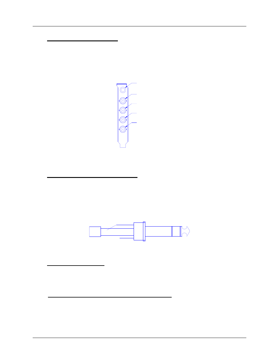
4.2 Sensor Connections
Once the SQM-242 is installed in the PC, connect the cable from the sensor oscillator to
the BNC jack on the SQM-242 card. Refer to the drawing in Section 4.0. Avoid running
the sensor wires near high voltage or noisy lines.
Sensor 1
Sensor 2
Sensor 3
Sensor 4
Control Outputs
4.3 Power Supply Connection
The connection to your evaporation power supply is done through a 1/4” Stereo Phone
Jack on the SQM-242 card. There are 2 control voltages on this connector, as shown in
the figure below. The ground is common to both channels. Power supply input
connectors vary. Consult your power supply manual.
Ground
(Sleeve)
Chan 1 (Ring)
Chan 2 (Tip)
4.4 Troubleshooting
Defective crystals or improper software setup causes most SQM-242 problems. Follow
the procedures below to identify and correct common problems.
4.4.1 No Readings, or Erratic Readings from Sensors:
Disconnect the deposition source supply. This eliminates the possibility that a noisy
source, or poor loop tuning, are causing an unstable PID loop. Verify that the sensors,
oscillator and cabling are connected as shown in Section 4.0.