KBC Networks WESII User Manual
Page 106
WESII User Manual
Manual-WESII-Rev1403
Copyright © KBC Networks 2014
Page 105 of 140
www.kbcnetworks.com
Signal Strength: This is the RSSI (Received Signal Strength Indication) ranging from 0-
100. The RSSI, is the measure of the strength of the RF connection between radios. The
RSSI number in the screen shot above is ‘70’ with the numbers within the parenthesis
showing the RSSI’s for the vertical (77) and horizontal (53) portions of the radio (ie. the
2x2 function of the MIMO). The vertical and horizontal RSSI figures can be used if two
separate directional antennas require individual alignment. Certain variables exist by
which this indicator is established. If line of sight, interference or other adverse site
specific conditions exist, the RSSI will be limited to a much lower number on the 0-100
scale. The RSSI in the above screen shot was attained when the radios were in very
close proximity on a bench test. When distance is increased between the radios and
other variables are introduced the number will drop significantly from the high numbers
shown. A reasonable RSSI for average deployments will be in the 40 to 50 range. A bare
minimum RSSI that KBC Networks recommends to maintain an RF link for constant
streaming video is no less than 20. If max TX and RX rates are established at lower
RSSIs then the system is performing as optimally as possible in a harsh RF environment.
Tx / Rx Rates: The rate of transmission and reception is auto-negotiated with the
opposite radio in the RF connection. The system attempts to establish a link at the
maximum rate of 162Mbps (in 40 MHz bandwidth) however, if the environment restricts
a connection at the maximum rate, the radios will attempt connection at the next lower
rate. It will continue to auto-negotiate the rate until a connection can be established.
Tx CCQ: Transmission Client Connection Quality – this value, shown as a percentage,
shows how effective the transmitted bandwidth being used is compared to the theoretical
maximum bandwidth.
Channel Width: The selected bandwidth from ‘BASIC WIRELESS – Radio 1’ is shown.
Other options include HT5 and HT20. The larger the bandwidth the lower number of
channel options available to use.
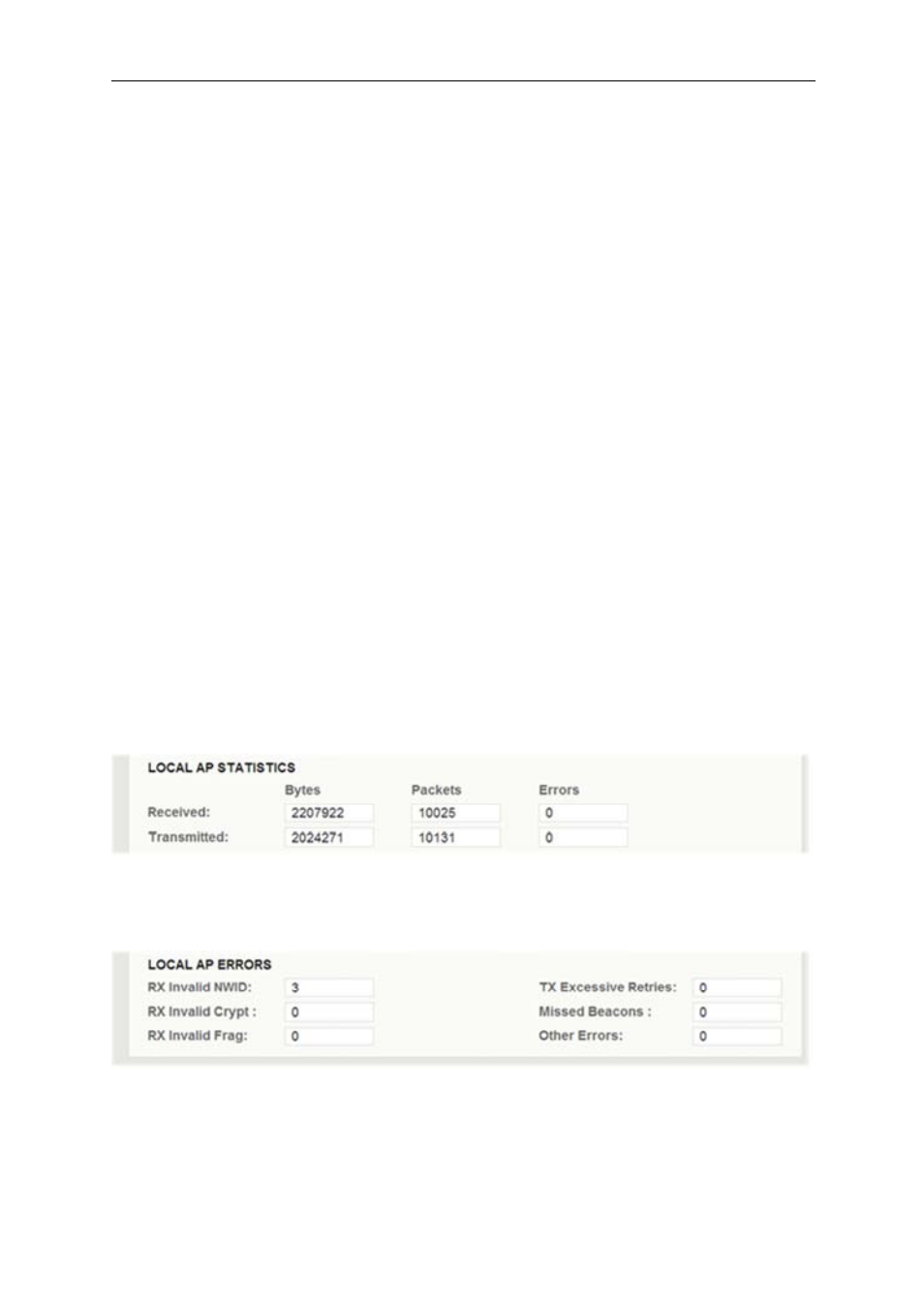
Local AP Statistics: The transmitted and received data packets over the RF connection
are recorded and viewable here. Any error will also be captured. The refresh button will
update the transmission statistics.
Local AP Errors: Any additional error and/or collision in the wireless traffic when a Host
is connected to a Client or group of Clients will be captured and displayed in this section
helping to identify the loss of data over the wireless link.