Connections, 1 physical connections – KBC Networks WESII User Manual
Page 26
WESII User Manual
Manual-WESII-Rev1403
Copyright © KBC Networks 2014
Page 25 of 140
www.kbcnetworks.com
6. Connections
6.1 Physical Connections
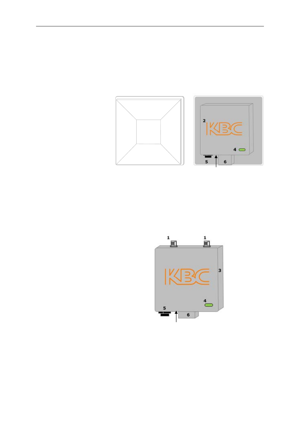
6.1.1 Integrated Patch Antenna Chassis
6.1.2 External Antenna Chassis
Rear view
Note:
See Section 11.2.2.3 for details of how to carry out a hard reset to default
settings.
1
Front view
Rear view
1. Patch antenna cover
2. Serial number label
3. Internal RF module
enclosure
4. Status LEDs
5. LAN port (RJ45)
6. Mounting block
7. Reset to default button
1. Antenna ports, attach screw down
omni-directional antennas (for directional
antennas, connect jumper LMR-200 cable)
2. Serial number label
3. Internal RF module enclosure
4. Status LEDs
5. LAN port (RJ-45)
6. Mounting block
7. Reset to default button
3
1. Patch an tenn a cover
2
1. Patc h antenna c over
7
7