Cable assembly, 1 strain relief assembly, 2 configuring the cable – KBC Networks WESII User Manual
Page 30
WESII User Manual
Manual-WESII-Rev1403
Copyright © KBC Networks 2014
Page 29 of 140
www.kbcnetworks.com
8. Cable Assembly
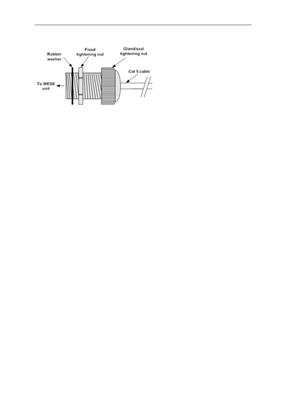
8.1 Strain Relief Assembly
1. Thread the Cat 5 cable through the hole in the gland.
2. Pull the cable through and crimp on the RJ45 connector – see section 8.2
3. Connect the RJ45 connector into the WESII’s LAN port.
4. Tighten the clamping nut until the Ethernet cable is secured in the connector until it
is hand tight.
Note:
the RJ45 connector does move slightly within the LAN port on the WESII unit this
allows the RJ45 connector to be connected to the Ethernet port more easily.
8.2 Configuring the Cable.
Note:
The total length of cable from the WESII to the Ethernet device cannot exceed
100m (325 feet); however, for a non-PoE WESII unit the PIM can be located anywhere
along the overall 100m of cable. KBC Networks recommends shielded Ethernet cables for
the cable connecting the PIM to the WESII unit. Any cable exposed to the elements
should also be outdoor rated.
1. Determine the length of cable that will be required and where the PIM will be
located.
2. Slide the weatherproof connector over the cable jacket before crimping the
connector. See Section 8.1 for the assembly instructions. If needed, see below for
color-code standards to configure the correct type of Ethernet cable.
Note:
Ethernet standard straight-through cable configurations used must be configured
to one of the Ethernet standards (568-A or 568-B) in order for the WESII system to
operate efficiently. Any deviation from one of the two standard configurations can lead to
undesired activity.