6 pmc 1 interface connectors (j11, j12, j13, j14), Table 5-6, Pmc 1 connector (j11) pin assignments – Artesyn MVME55006E Single Board Computer Installation and Use (July 2014) User Manual
Page 90: Pmc 1 interface connectors (j11, j12, j13, j14), Connector pin assignments
Connector Pin Assignments
MVME55006E Single Board Computer Installation and Use (6806800A37J)
90
5.2.6
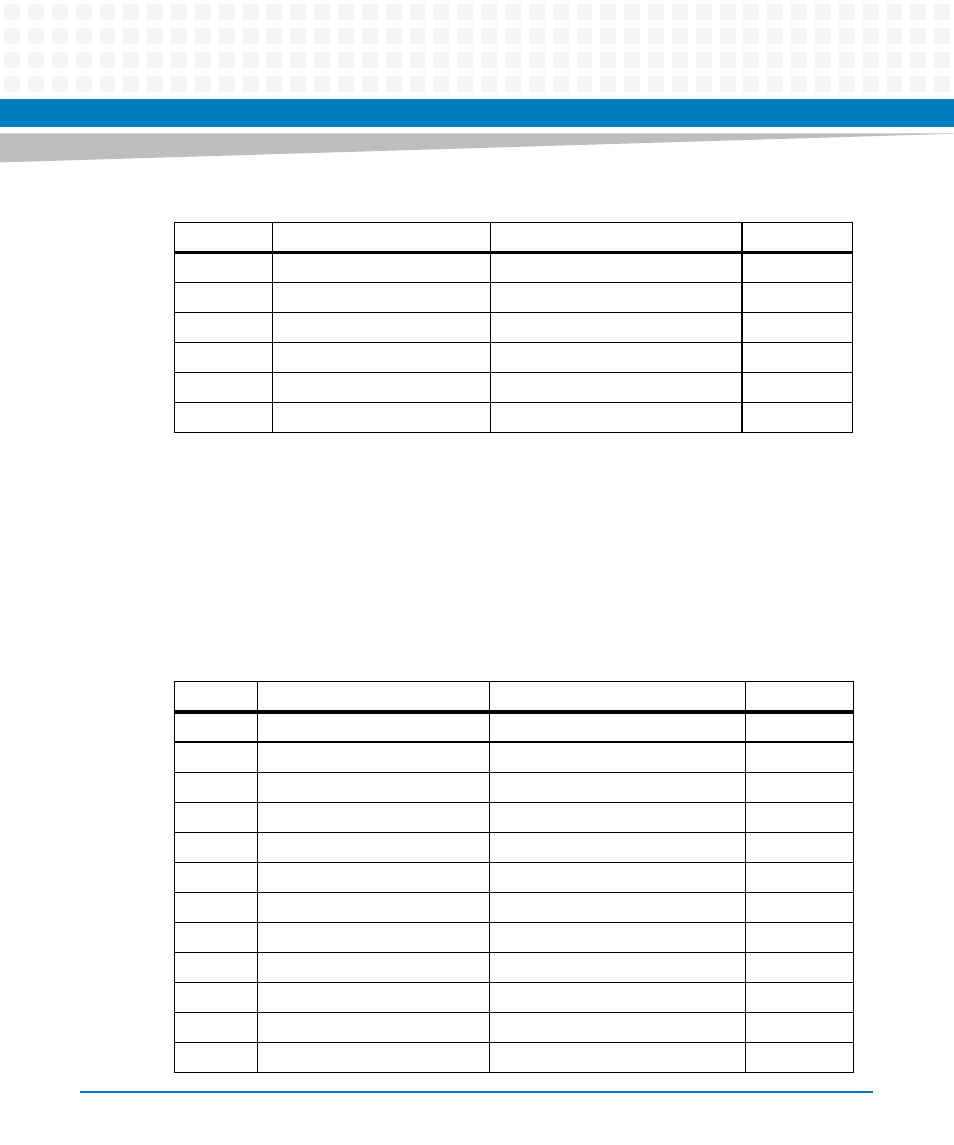
PMC 1 Interface Connectors (J11, J12, J13, J14)
There are four 64-pin SMT connectors for the PMC 1 slot on the MVME5500 to provide a 32/64-
bit PCI interface and optional I/O interface.
If a PMC module is plugged into PMC slot 1, the memory mezzanine card cannot be used
because the PMC module covers the memory mezzanine connector.
5
QREQ_L
2.5V_VIO
6
7
CPUTCK
OPTPU_2.5v
8
9
CPUTMS
NC
10
11
SRESET_L
NC
12
13
CPURST_L
KEY (no pin)
14
15
CHECKSTPO_L
GND
16
Table 5-5 CPU COP Connector (J5) Pin Assignments (continued)
Pin
Signal
Signal
Pin
Table 5-6 PMC 1 Connector (J11) Pin Assignments
Pin
Signal
Signal
Pin
1
TCK
–12V
2
3
GND
INTA#
4
5
INTB#
INTC#
6
7
PRESENT#
+5V
8
9
INTD#
PCI_RSVD
10
11
GND
+3.3Vaux
12
13
CLK
GND
14
15
GND
GNT#/XREQ0#
16
17
REQ#/XGNT0#
+5V
18
19
VIO
AD31
20
21
AD28
AD27
22
23
AD25
GND
24