Theory of operation -1, 0 theory of operation -1 – Comtech EF Data DD240XR Rev Е User Manual
Page 19
DD240XR High-Speed Digital Demodulator
Operation
MN-DD240XR – Rev. E
3-1
Theory of Operation
3
3.0 Theory of Operation
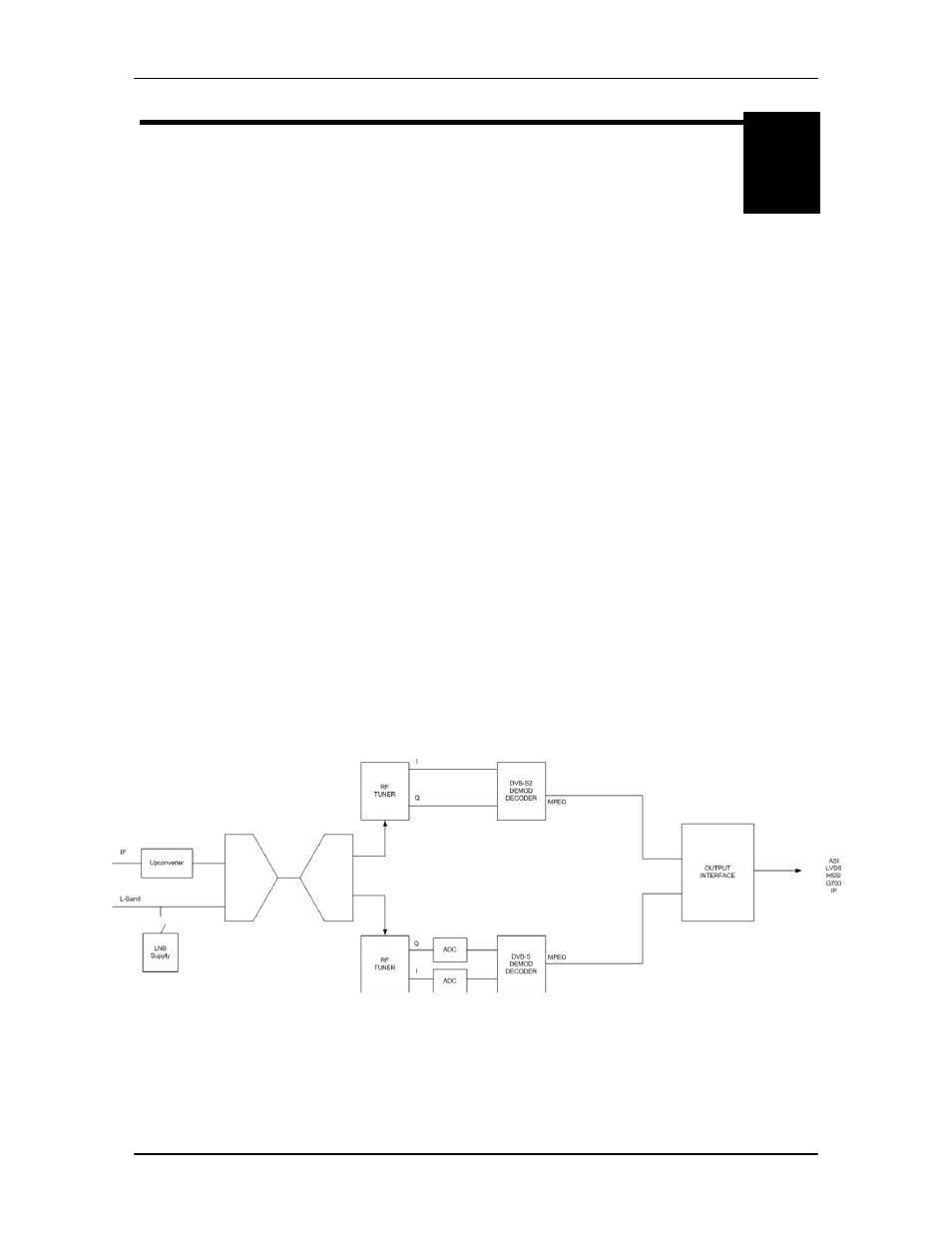
The basic theory of operation for each platform is similar. The DD240XR is capable of supporting
L-band from 950-2150 MHz and can be upgraded to include IF frequencies of 50-180 MHz in the
same package. If the unit is configured to receive analog signal in the IF band of 50-180 MHz, the
signal is converted to L-band. The L-band signal is then tuned and digitally demodulated. The
incoming I&Q symbols are then filtered decoded, and mapped to data bits. The network
specification selected will determine if the data stream supports DVB-S or DVB-S2 formats.
The DVB-S Network specification complies with both EN300-421 and EN301-210 ETSI
specifications. EN300-421 supports QPSK demodulation and EN301-210 supports higher
demodulation rates of 8PSK and 16QAM. The resulting data stream is FEC decoded by the
Viterbi (K=7) inner convolutional/trellis decoder, de-interleaved and further FEC decoded by the
outer Reed Solomon 204/188 decoder.
The DVB-S2 Network specification complies with the next generation DVB open standard
supported by EN302-307. At the core of this standard is a powerful Bose-Chaudhuri-
Hocquenghem BCH decoding and concatenated Low-Density Parity Check (LDPC). The
DD240XR only supports normative features identified by the DVB-S2 Broadcast services. The
Broadcast Services mode of operation supports Constant Coding and modulation (CCM) system
and single transport streams. Operating in this mode allow for a variety of FEC rates to be used
with QPSK, 8PSK and 16APSK modulation schemes.
The decoded data is then sent through a deframer to provide terrestrial data that is either
unframed, 188 byte DVB format or 204 byte DVB format. Based on the type of terrestrial interface
installed, the data stream is re-clocked through an optional Doppler buffer, serialized and
converted through the appropriate physical layer interface. A functional block diagram is shown in
Figure 3-1.
Figure 3-1. Functional Block Diagram