B.1.2 1:2 redundancy mode – Comtech EF Data HPOD User Manual
Page 132
HPOD C-, X-, Ku-Band High-Power Outdoor Amplifier
MN/HPOD.IOM
Appendix B
Revision 8
B–2
In 1:1 applications, the BU also stores an offset value, to be used when the BU replaces the
active unit. This offset may be set with the GOF= command. When the online unit is being
“backed up” the BU’s attenuator will be set to this value. This value may be different than the
attenuation value of the online unit to compensate for any gain mismatch between the BU and
online units.
To calibrate, do these steps:
Step
Task
1
Identify the unit with the most gain.
2
Calculate the actual error.
3
To compensate for the error, set the GOF= command in the unit having the highest error. For example – If
SSPA 1 has 70 dB of gain, and BU SSPA 2 has 72 dB, send the GOF=2.00 command to the BU SSPA 2 to
store these values.
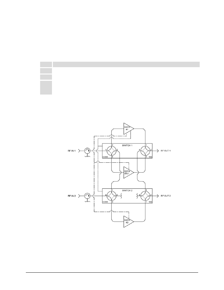
B.1.2 1:2 Redundancy Mode
Figure B-1 shows the block diagram for an HPOD 1:2 Redundancy System. For the purpose of
example, this figure shows a C-Band system.
Figure B-1. HPOD C-Band 1:2 Redundancy System Block Diagram
In 1:2 redundancy mode there is a dedicated BackupUnit (designated as BU) as determined by
the cable position. In this configuration, the BU is responsible for monitoring the two online
units for communications and summary faults.