5 electrical control interface connection group, 1 ‘j4 | redundant loop’ connector – Comtech EF Data HPOD User Manual
Page 33
HPOD C-, X-, Ku-Band High-Power Outdoor Amplifier
MN/HPOD.IOM
External Connectors and Pinouts
Revision 8
2–7
2.5
Electrical Control Interface Connection Group
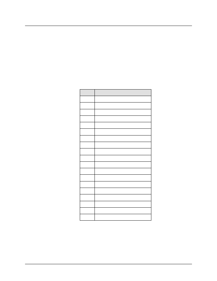
2.5.1 ‘J4 | REDUNDANT LOOP’ Connector
The ‘J4 | REDUNDANT LOOP’ connector is located near the waveguide output and is used only
in configurations where the SSPA controls waveguide switching.
In alternate configurations, such as “chain switching”, another system block or external M&C
controls the waveguide switching. In this case, the connector remains unused and the protective
cap should be left attached. The pinout specification is shown in Table 2-5.
Table 2-5. ‘J4 | REDUNDANT LOOP’ Connector Pinout
Pin
Name
A
SW_CMD_A1
B
SW_CMD_COM
C
SW_CMD_A2
D
SW_IND_A1
E
SW_IND_A2
F
SW_CMD_B1
G
SW_CMD_B2
H
SW_IND_B1
J
SW_IND_B2
K
ADDR_1
L
ADDR_2
M
COM
N
RED_1_1
P
RED_1_2
R
SMFLT_1_IN
S
SMFLT_2_IN
T
SMFLT_OUT
U
RED_TXD
V
RED_RXD