Limitorque actuation systems – Flowserve MX-85 Actuator User Manual
Page 32
Flow Control
Limitorque Actuation Systems
24
MX-85/140 Maintenance and Spare Parts
FCD LMAIM1341-00
STEP 6
Set screw adjustment. Install drive sleeve, base-
plate, clutching and handwheel worm gear compo-
nents. Assure the clutch lugs are fully engaged to
the motor worm gear lugs before the adjustment.
With declutch lever resting on cap pad (not the
set screw) place declutch cap assembly (1-4) into
housing without mounting screws. Rotate cap
assembly clockwise until declutch cam is resisted
by the roller, clutch ring and clutch combination.
Holding the declutch lever, rotate the set screw
clockwise thru declutch cap, (this will rotate the
cap counterclockwise) until the cap mounting
holes are inline with the taps in the housing. Install
declutch assembly mounting screws. Then rotate
set screw counterclockwise ¼ ±
1
⁄
8
turn. Adjustment
is complete.
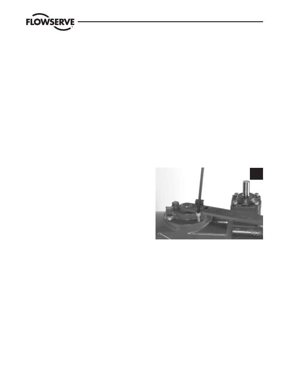
STEP 7
Fit the four M8 screws to retain the declutch
assembly cover (#5-1) on the housing. Tighten
using a 6 mm hex key. Picture 7 shows the four
screws.
7