Flowserve MX-85 Actuator User Manual
Page 65
Flow Control
Limitorque Actuation Systems
FCD LMAIM1341-00
MX-85/140 Maintenance and Spare Parts
57
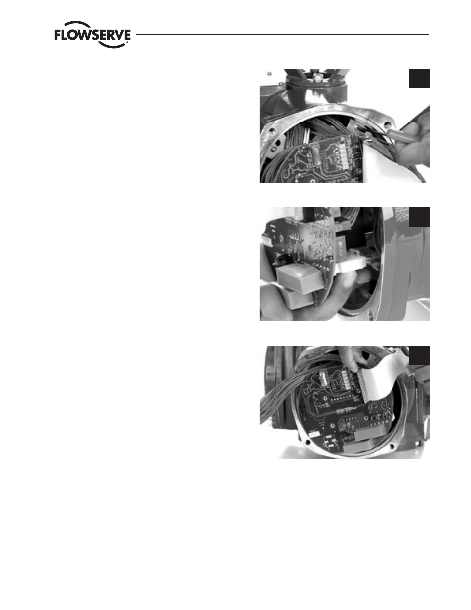
STEP 5
Position power assembly over the three mounting
screw heads (#1-45). Rotate the subassembly in
clockwise (CW) direction until all three screws are
seated in the key slots. (The keyhole slots in the
mounting plate (#8-1) are spaced in such a way
that the control module assembly will mount in
only one position).
Tighten the three screws (#1-45) with a 3 mm
hex key.
5
STEP 6
Connect the AMP power connector to the fuse sec-
tion on the Power board (P1).
6
STEP 7
Connect the 10-pin encoder ribbon cable to plug
P3 on the Main/LCS processor board. Align the
polarization plug with the slot in the center of
connector J1.
7
STEP 8
Connect the 4-pin Molex harness to plug P4 on the
Main/LCS processor board.