1 removal – Flowserve MX-85 Actuator User Manual
Page 48
Flow Control
Limitorque Actuation Systems
40
MX-85/140 Maintenance and Spare Parts
FCD LMAIM1341-00
4.7.1 Removal
First Remove
1. Remove actuator from mounting adapter.
2. Drain oil.
3. Remove thrust base (subassembly #10) - if fitted. (See Section 4.4.1.)
4. Remove motor (subassembly #4). (See Section 4.1.1.)
5. Remove worm shaft (subassembly #3). (See Section 4.6.1.)
6. Remove side-mounted handwheel (subassembly #16). (See Section 4.3.1.)
7. Remove handwheel worm gear (subassembly #12). (See Section 4.8.1.)
8. Remove clutch and clutch ring (subassembly #16). (See Section 4.9.1.)
9. Remove handwheel declutch (subassembly #5). (See Section 4.2.1.)
10. Remove base plate (subassembly #11). (See Section 4.5.1. or Section 4.7.3)
c
WARNING: The drive sleeve assembly may slip and fall out of housing when removing baseplate assembly.
Hold drive sleeve assembly in from opposite end when removing baseplate assembly. See optional drive sleeve
and baseplate removal Section 4.7.3 and 4.7.4.
STEP 1
c
WARNING: Potential to operate while danger-
ous mechanical parts are exposed during
subassembly removal. To prevent injury, turn
off all power sources to actuator before remov-
ing drive sleeve assembly. Power sources may
include: main power or control power.
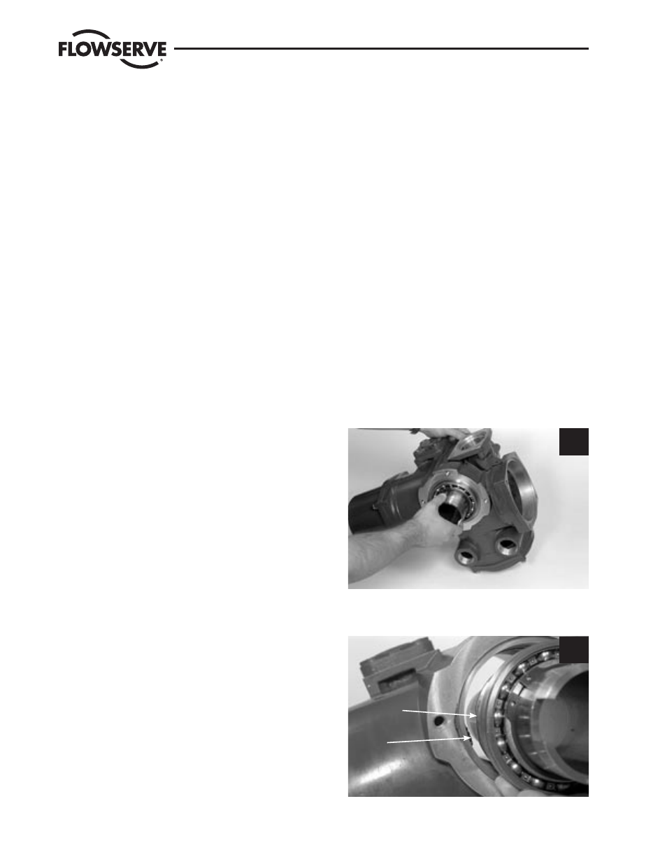
Once all other subassemblies are removed, pull out
the drive sleeve assembly (#2) until the lower bear-
ing (#2-4) is released from the actuator housing.
Remove drive sleeve assembly from actuator.
1
STEP 2
(Viewed from baseplate side of actuator)
Tip: To avoid interference between drive sleeve
assembly and encoder drive cartridge (subassem-
bly #14), turn flat on worm gear to be parallel and
on same side as encoder bevel gear.
2
Worm
gear flat
Encoder
drive
cartridge