2 removal – Flowserve MX-85 Actuator User Manual
Page 67
Flow Control
Limitorque Actuation Systems
FCD LMAIM1341-00
MX-85/140 Maintenance and Spare Parts
59
STEP 12
Using a screwdriver, install the four M4 screws (#7-
44) to retain the LCS/Main board inside the ACP
cover. Select the screws based upon the number
of option boards in the actuator; M4 X 6 mm for
standard set, M4 X 25 mm for one option board,
and M4 X 45 mm for two option boards.
Ensure O-ring (#7-21) is intact on the ACP spigot/
pilot. Hold the ACP in front of the control module
assembly and connect 40-pin ribbon connector
plug to connector J1 on the power board. This
ribbon cable is to always remain connected to the
LCS/Main board. Align the polarization tab of the
ribbon connector with the slot in J1.
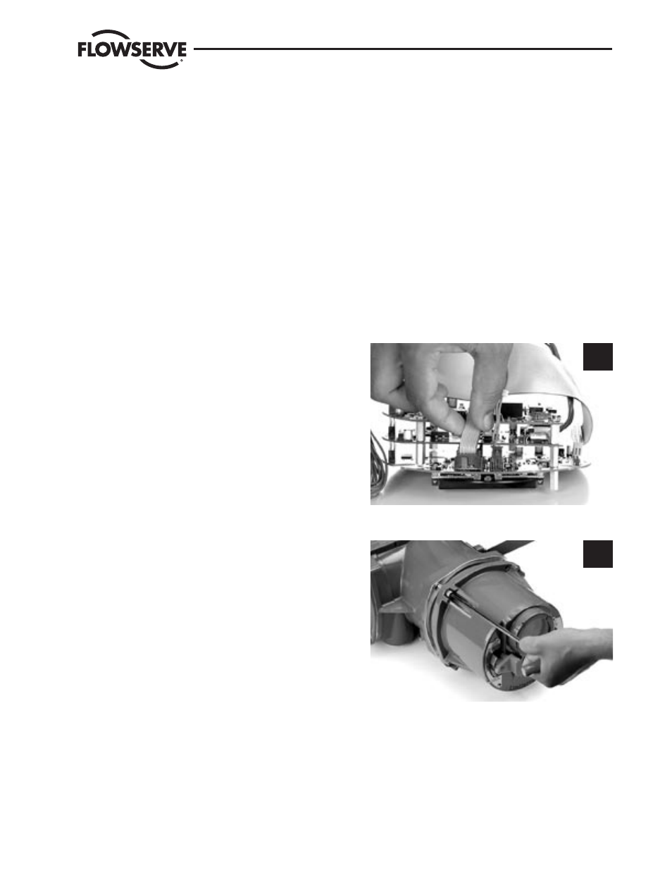
STEP 13
a
CAUTION: Potential to pinch cables. When
remounting ACP cover, take special care not to
pinch ribbon cables.
Dress the cables as shown being careful to position
wires so that they pass perpendicularly over the
housing flange.
13
STEP 14
NOTE: The face of the ACP may be installed in
any one of four 90° incremental positions. When
changing ACP position, avoid over-twisting the
ribbon cable.
Rotate the ACP until the display orientation of the
front face is correct for normal viewing, then slide
the ACP assembly into the actuator housing.
14
5.2.2 Removal
For removal, follow installation instructions in reverse.