Control and interface panels – Fluke Biomedical RF303 User Manual
Page 17
Advertising
Introduction and Specifications
Control and Interface Panels
1
1-7
Control and Interface Panels
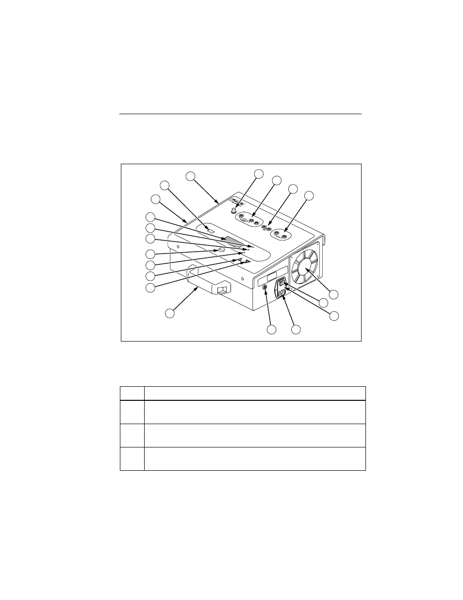
Figure 1-1 and Table 1-2 describe the controls and interfaces of the Analyzer.
RF-303
ELECTR
OSURGICAL ANAL
YZER
9
19
20
10
11
12
13
2
1
3
4
6
7
8
18
15
14
17
16
5
exz14.eps
Figure 1-1. Analyzer Control and Interface Panels
Table 1-2. Controls and Connections
Item
Name / Description
1 Display
Backlit, numeric, 4-digit LCD
2
Power Indicator (WATTS) Lamp
Displays reading in watts.
3
Current Indicator (mA) Lamp
Displays readings in milliamperes (mA).
Advertising
See also other documents in the category Fluke Biomedical Equipment:
- 7000DP Impulse Supplement (12 pages)
- 7000DP Impulse Getting Started (36 pages)
- 7000DP Impulse (92 pages)
- 06-526-2200 (26 pages)
- 07-417 (16 pages)
- 07-443 (14 pages)
- 07-451 (8 pages)
- 07-487 (12 pages)
- 07-453 (24 pages)
- 07-555 (8 pages)
- 07-553 (10 pages)
- 07-605-7777 (8 pages)
- 07-444 (46 pages)
- 07-618 (10 pages)
- 07-600 (6 pages)
- 07-591 (8 pages)
- SigmaPace 1000 (154 pages)
- 07-653 (8 pages)
- 07-633 (20 pages)
- 07-649 (14 pages)
- 07-661-7662 (12 pages)
- 07-645 (14 pages)
- 10100AT (80 pages)
- 07-644 (10 pages)
- 18-203 (4 pages)
- 07-621 (12 pages)
- 07-647 (12 pages)
- 18-207 (8 pages)
- 18-216-1000 (10 pages)
- 18-220 (10 pages)
- 18-228 (8 pages)
- 18-223 (18 pages)
- 18-229-1313 (6 pages)
- 18-250 (8 pages)
- 18-252 (6 pages)
- 18-303 (6 pages)
- 35035 (19 pages)
- 6000-528 (18 pages)
- 35080B (70 pages)
- 6000-529 (16 pages)
- 35080M (64 pages)
- 6000-530B (16 pages)
- 57-436 (12 pages)
- 57-440 (12 pages)
- 57-402 (32 pages)