Prog 3/7 - internal diagnostics, Prog 2/6 - dc module diagnostics, Prog 1/5 - relay module diagnostics – GAI-Tronics L3149B C200 Advanced Deskset User Manual
Page 44
Installation
L3149B (C200) Advanced Tone Remote Desk Set
38
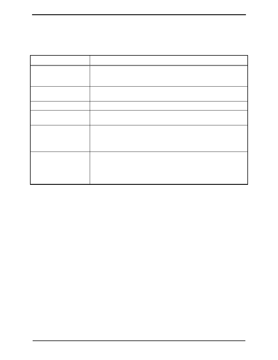
PROG 2/6 - DC Module Diagnostics
This mode allows the dc board to be exercised with both positive and negative currents and sets the
DCLOTL. The threshold for DCLOTL is adjustable, but is factory preset for most installations. The
asterisk (*) is present in the lower right corner if the line voltage is above the preset DCLOTL threshold.
Button(s)
DC Module Diagnostics Mode Function:
VOLUME
Up or
VOLUME
Down
Increases/decreases the dc value sent to the dc module. This value
determines the dc current level and is a hexadecimal number ranging from
00 (lowest current) to 0x3F (highest current).
LOCK
+
VOLUME
Up or
LOCK
+
VOLUME
Down
Works in the same manner as the function above, but increases or decreases
the value by 10 rather than 1.
TRANSMIT
Exits the dc module diagnostic mode.
MONITOR
Toggles to the polarity of the current being generated. The display shows
+ for positive and − for negative polarity.
LOCK
+
PROG
1/5
Allows the DCLOTL threshold to be set. In order for this setting to be
done properly, a dc supply must be connected to the line pair with 3 volts.
When
LOCK
+
PROG
1/5
to pressed, the unit reads the dc voltage on the
line and save the value for future DCLOTL operation.
LOCK
+
PROG
4/8
Like
LOCK
+
PROG
1/5,
this key sequence sets the DCLOTL threshold.
However, no dc supply is needed. To set the threshold, set the current out
into the proper line load (typically 8 kilohms) by using the
VOLUME
Up or
Down buttons. When the proper current is reached, press
LOCK
+
PROG
4/8.
The unit reads the voltage for future DCLOTL operation.
PROG 1/5 - Relay Module Diagnostics
Allows the relay I/O module to be exercised. The display indicates the status of:
Inputs – IN
Relay – OUT
By pressing any key (except
TRANSMIT
) starting at relay1 and progressing up to relay 4, the relays close
and then open. The numeral 1 in the OUT position indicates the relay should be closed. LEDs on the
relay I/O module also indicate the status of each relay.
To exercise the inputs, each input can be grounded. This is indicated by a numeral 1 in the IN position
associated with the input. As each input is shorted to ground, the corresponding 1 in the IN position
indicates a 0. To exit the relay module diagnostics, press
TRANSMIT
.