Rs-232 connector pinout – Gasboy FuelOmat system 8 Popt Commverter User Manual
Page 37
NOTE
This module does not require opening the Commverter to
view the LEDs status and indications. The LEDs are
displayed through the holes of the Commverter cover.
The LEDs indication can be seen in the appropriate
column above the module installation position. The
column holes should be seen at the right-hand side from
the vents of the Power Supply, from top down.
LEDs Indication
Connector Side
Channel 2
Rx
D8
Channel 2
Tx
D7
Channel 1
Rx
D3
Channel 1
Tx
D2
Blank
Blank
LED Blinking
– Communication on
LED Off
– No communication
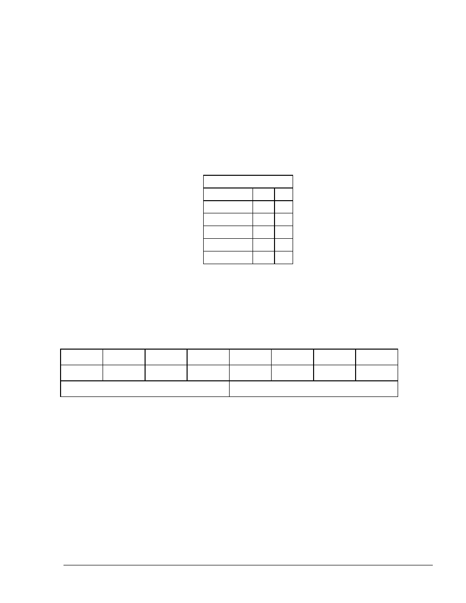
2.6.1.
RS-232 Connector Pinout
The following pinout is required for the LAN to RS-232 application.
8 7 6 5 4 3 2 1
G
D I/O
Rx
Tx
G
D I/O
Rx
Tx
Channel 2
Channel 1
8 Port CommVerter Operation and Installation Manual
33