Rs-422 connector pinout, Subrs422 module application – Gasboy FuelOmat system 8 Popt Commverter User Manual
Page 62
NOTE
There is no external indication of the LEDs status.
Remove the Commverter cover to reveal the module
LEDs.
LEDs Indication
Connector Side
Channel 1
Rx
D4
Channel 1
Tx
D1
LED Blinking
– Communication on
LED Off
– No communication
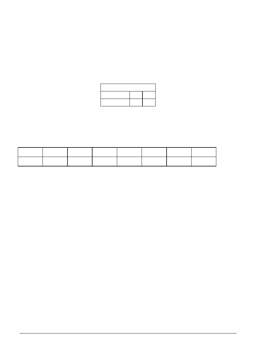
2.10.2. RS-422 Connector Pinout
The following pinout is required for the LAN to RS-422 application.
8 7 6 5 4 3 2 1
G
T-
T+
R-
R+
2.10.3. Sub-RS422 Module Application
The RS422 Module has an additional sub-RS422 module on top of it (connector CN4). This
sub-module provide data transmission conversion into RS422 for Channel 2.
The pinout of the connection is the same as for the RS422 module. Pins 1 to 5 (GND) only are
active, to provide RS422 transmission).
8 Port CommVerter Operation and Installation Manual
58