Table 2-7. pulse divider pinout – Gasboy FuelOmat system 8 Popt Commverter User Manual
Page 72
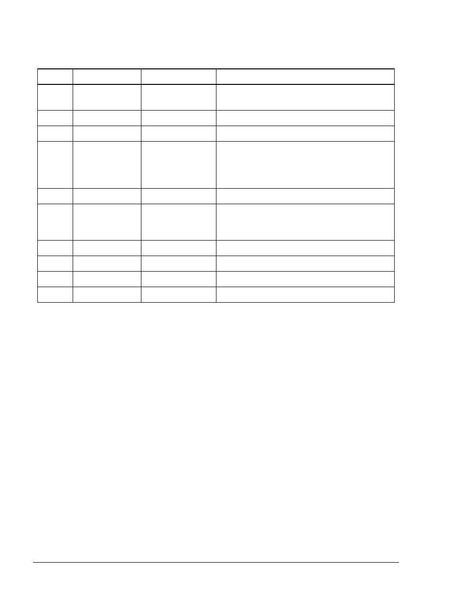
Table 2-7. Pulse Divider Pinout
Description
Name
Wire Color
Pin#
Input voltage from CommVerter to Pulse
Divider (10-28VDC)
DC INPUT
RED
1
Ground
GROUND
BLACK
2
Input pulses from pulser to Pulse Divider
SIGNAL IN 1
BROWN
3
Input pulses from pulser to Pulse Divider
(when input signal is differential).
Threshold voltage applied to Pulse Divider
when Input pulses are other than differential
SIGNAL IN 2
GREEN
4
N/A
DC OUT
ORANGE
5
1.4VDC reference voltage connected to the
green wire only in cases where Option B is
utilized (otherwise unused)
REF/V OUT
GRAY
6
Output signal divided by 2
:2 OUT
VIOLET
7
Output signal divided by 4
:4 OUT
YELLOW
8
Output signal divided by 8
:8 OUT
BLUE
9
Output signal divided by 16
:16 OUT
10
WHITE
8 Port CommVerter Operation and Installation Manual
68