D event input configuration, Event input configuration, Figure 73: event cable wiring diagram – NavCom SF-3050 Rev.A User Manual
Page 151: Table 27: event wiring connections, D ...................... event input configu, Ration
SF-3050 User Guide – Rev A
D-149
D ...................... Event Input Configu
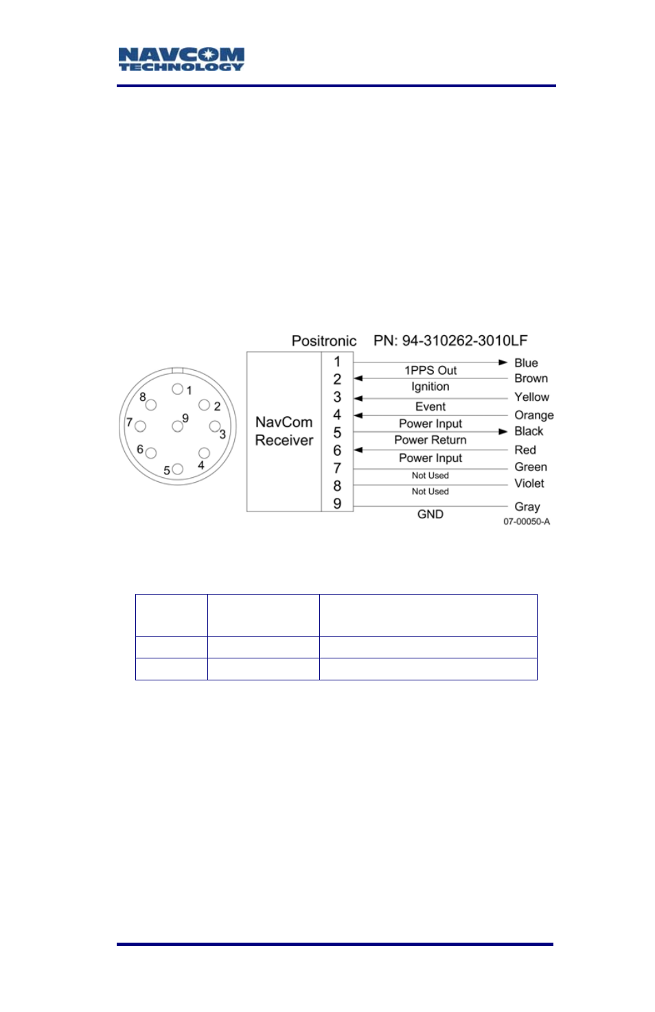
Figure 73 details the wiring of the supplied Event
cable assembly NavCom part number P/N 94-
310262-3010LF.
Refer to Chapter 3/Event for detailed electrical
specifications.
ration
Table 27 details the wiring configuration required for
Event pulse sensing.
am
Figure 73: Event Cable Wiring Diagr
Table 27: Event Wiring Connections
Pin #
Signal
Name
Event Sync Wiring
3
Event
Tie Event to Ground
9 Ground
N/A
Once the cable is wired to correspond with the e
pulse requirements, configure the receiver to output
vent
e containing a time mark, referenced to
the time kept within the receiver, indicating when the
the messag
event is sensed (EVENTLATCH, EVENTLATCHA).
Messages EVENTLATCH and
EVENTLATCHA are described in the
Sapphire Technical Reference Manual (see
Related Documents in the fore-matter).