Chapter 4 installation, Antennae, Chapter 4 – NavCom SF-3050 Rev.A User Manual
Page 95: Installation, Figure 55: rover, base, airborne gnss antennae
4-93
SF-3050 User Guide – Rev A
Chapter 4 .................................Installation
This chapter provides guidance on hardware
stallation for optimum performance.
ntennae
The 5/8 inch BSW threaded antenna mount has a
epth of 16mm (0.63 inch).
is possible to remove the 5/8 inch BSW threaded
lloy insert to reveal a secondary means of mounting
he antenna, a 1-14UNS-2B thread with a depth of
6mm (0.63 inch). This is a typical marine industry
ount for navigation antennas.
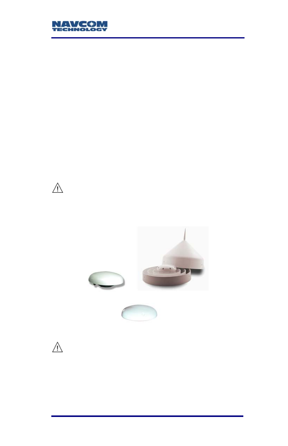
Figure 55: Rover, Base, Airborne GNSS Antennae
in
A
d
It
a
t
1
m
The BSW insert is secured in-place with an
ad
the
characteristics of the antenna mount.
hesive, and its removal will change
shock and vibration sustainability
Do not loosen or remove the Phillips screws
on the base of the antenna for mounting
purposes. This will VOID the warranty and
compromise the environmental seal of the
antenna, leading to internal damage.