Indicator panel, Figure 54: sf-3050 indicator panel – NavCom SF-3050 Rev.A User Manual
Page 91
SF-3050 User Guide – Rev A
3-89
variety of Time/ Mark applications where relative
timing is required.
Specifications:
25ns relative a
ccuracy
100ns absol
5V TTL Logic level outp
Better than
ute accuracy
ut
1 PPS Output Impedance > 50 Ohms
S, range 10
Pulse width, default 100m
– 999mS
9mS
Rising or Falling Edge Synchronization
Pulse delay, default 0mS, range 0 – 99
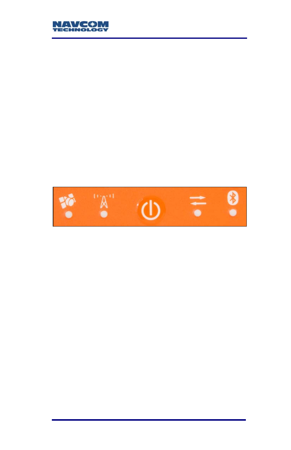
In icator Panel
d
Figure 54: SF-3050 Indicator Panel
The indicator panel provides a quick status view of
the GNS
e signal
tch for
riod
S navigation/operating mode, StarFir
strength, the On/Off (I/O) switch, data I/O and
logging, and Bluetooth connectivity, respectively.
To power the unit on or off, depress the I/O swi
more than 2 seconds. All LEDs illuminate for a pe
of 3-5 seconds during power-up of the GNSS sensor.
In this chapter, refer to the section, Proper
Shutdown of SF-3050, for details on powering
off the unit.