Abase station uhf boost radio, A base station uhf boost radio, Figure 61: boost radio wiring diagram – NavCom LAND-PAK Rev.F User Manual
Page 108: A ................. base station uhf boost radio
LAND-PAK™ User Guide – Rev. F
A-109
A ................. Base Station UHF Boost Radio
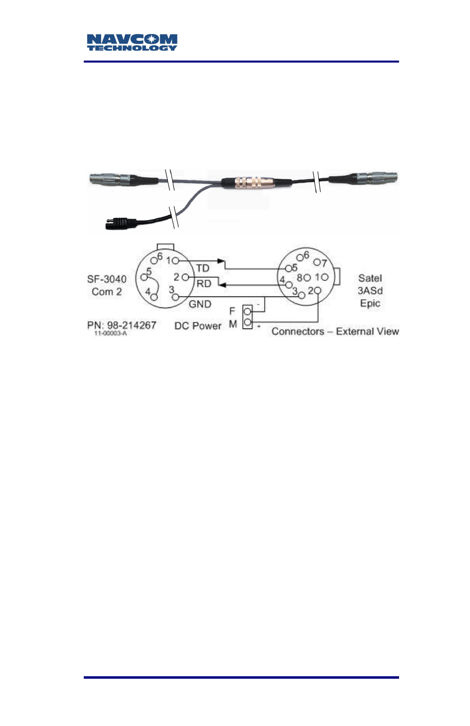
The radio connects to the SF-3040 Com 2 port with
the supplied cable (PN: 98-214267).
Figure 61: Boost Radio Wiring Diagram
The six pin connector is a Lemo PN: FGA-0K-306-
CYCC.5CZ. The eight pin connector is a Lemo PN:
FGA-1B.3D8.CLAD52Z. Each cable segment is 2ft
(0.6m) long.
The factory-set central RF frequency is listed with the
serial number on the radio modem. The RF frequency
can be set within 1MHz of the central frequency, at 25
kHz increments.
If tuning beyond 1 MHz is necessary, the user must
ship the radio to the manufacturer’s factory for
hardware modification. Any shipping and customs
charges are the responsibility of the customer.
Check with local regulatory authorities to
ensure compliance.