Verilink DPRI 2922 (880-503142-001) Product Manual User Manual
Page 46
Configuring the DPRI 2922 Via the NCM 2000 Craft Interface
3-16
Verilink DPRI 2922
One of the functions of the Data Port Configuration Menu is to set
the communication handshake leads between the DPRI data port
and your equipment (DTE).
•
When the leads are set to “LOW”, DCE signals follow DTE
signals during handshaking.
•
When the leads are “HIGH”, the signal is always on, always
ready.
Note that the lead options swap inputs and outputs between the
DCE or DTE data port modes.
There are three controllable diagnostic leads at the data port
(which are set up via the Data Port Diagnostics Menu, Figure 3-20):
•
RLB—Remote Loopback
•
LLB—Local Loopback
•
TM—Test Mode.
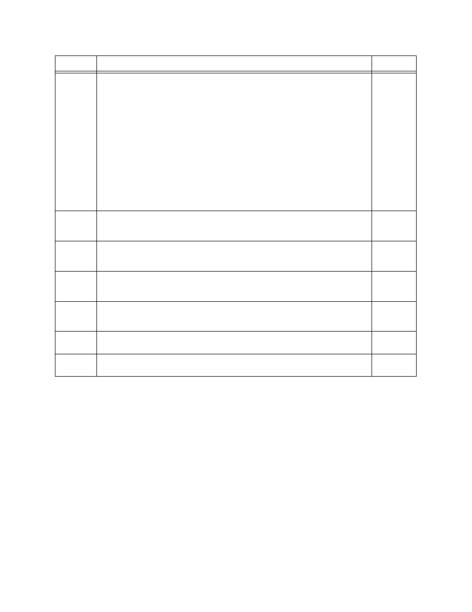
Cn
Clock Option: Use this option to select one of the following:
Serial Transmit (ST): In this mode, the normal non-inverted phase of the Serial
Clock Transmit (SCT) is used to clock data from the DTE into the DPRI module’s
data port transmit buffer. This is the default setting.
Inverted Serial Transmit (INV ST): In this mode, the inverted phase of the SCT is
used to clock data from the DTE into the DPRI module’s data port transmit
buffer—when compensating for phase delays (caused by using long cables) and
when the far end is receiving bit errors. TT is a better alternative.
Terminal Timing (TT): In this mode, Serial Clock Transmit Extension (SCTE) is
used to clock data from the DTE into the DPRI module’s data port transmit
buffer. Normally, this clock is looped by the DTE from the SCT signal. It is the
preferred timing method because the transmit clock and data are always in sync
regardless of cable length. Unfortunately, this signal is not provided by all DTE
equipment. Set this option in tail-circuit timing applications (when the data port
receives timing from another circuit).
1) ST
2) INV ST
3) TT
Ln
Control Line Indicator (On E1 networks only): Use this option in the data port
interface for flow control. LOW indicates that the port’s signal follows the DTE
signal. HIGH indicates that the port’s signal is always on.
1) LOW
2) HIGH
SRn
Data Set Ready (DSR): This is a DCE control lead. LOW indicates the port signal
follows the DTR signal. HIGH indicates the port signal is always on. Data
Terminal Ready (DTR): This is a DTE control lead.
1) LOW
2) HIGH
SSn
Clear to Send (CTS): This is a DCE control lead. Request to Send (RTS): This is a
DTE control lead. LOW indicates the port signal follows the RTS signal. HIGH
indicates the port signal is always on.
1) LOW
2) HIGH
SDn
Data Carrier Detect (DCD): This is a DCE control lead. LOW indicates this signal
follows the state of the network port to which the data port is attached. HIGH
indicates the port signal is always on.
1) LOW
2) HIGH
SMn
Test Mode (TM): This is used with a test set for diagnostics, and it should
normally be configured as LOW. This is a DCE control lead.
1) LOW
2) HIGH
X
Exit the Data Port Configuration menu and return to the Configuration Menu,
Command
Description
Options