Data port leds, System led, Data port leds -7 system led -7 – Verilink DPRI 2922 (880-503142-001) Product Manual User Manual
Page 85
Troubleshooting
Verilink DPRI 2922
4-7
Data Port LEDs
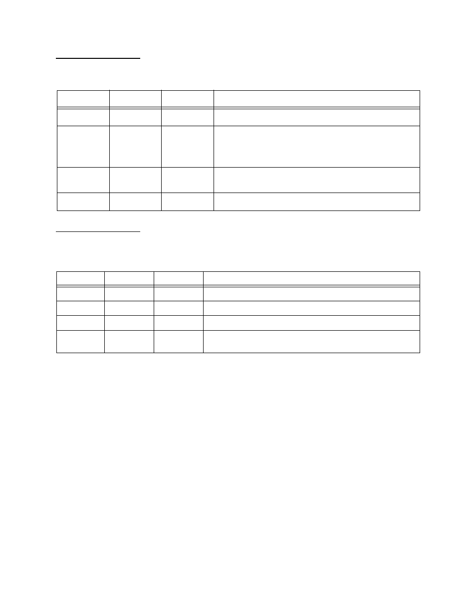
Data Port LEDs 1 and 2 display the status for their respective ports.
Table 4-3
Data Port LED Indicators
System LED
The System LED displays node controller assignments and node
communication conditions.
Table 4-4
System LED Indicators
State
Color
Alarm Class
Possible Error Condition
Solid
Green
All okay
None. (DTE connected and in sync)
Solid
Red
Major
Port active; Signal designated for LOS is not detected. For
example, if you have enabled DTR monitoring (to detect a Loss
of Signal) and you disconnect the cable, a major alarm is
declared.
Solid
Amber
Diagnostic
mode
Port is active and in loopback.
Off
None
None
Port is not enabled.
State
Color
Alarm Class
Possible Error Condition
Solid
Green
None
Module is okay and another module is the shelf controller.
Solid
Red
Critical
System failure. You may need to reseat the card in the shelf.
Off
None
None
Module is not on; no power.
Flashing
Green None
The module is acting as the controller (that is, it is the shelf
master controlling the ACP bus usage in the shelf).