Isdn pri configuration menu, Isdn pri configuration menu -16 – Verilink DPRI 2922 (880-503142-001) Product Manual User Manual
Page 47
Configuring the DPRI 2922 Via the NCM 2000 Craft Interface
Verilink DPRI 2922
3-17
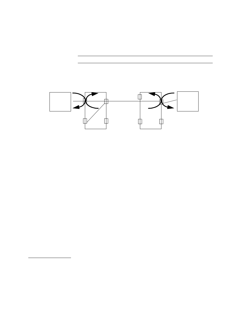
During normal operation, these leads should be set to LOW. By
connecting a test set to the data port, the RLB and LLB leads can be
forced HIGH individually. Resulting loopbacks are shown in the
following diagram. The status display changes to HIGH for these
leads.
NOTE: These leads are only useful in DCE mode.
Figure 3-9 Loopbacks
•
In DCE mode, the leads TM, DSR, DCD, and CTS can be forced
HIGH while connected to a test set to check that each lead is
operating properly.
•
In DTE mode, the leads DTR, RTS, LLB, and RLB can be forced
HIGH while connected to a test set to check that each lead is
operating properly.
In Figure 3-8, the parameters enclosed in the grey box are port
status listings. The first four lines show the state of the incoming
handshake leads. “HIGH” means incoming handshake signals are
detected on that lead, and “LOW” means no handshake signaling is
detected. In DCE mode, if the TM lead is “HIGH,” the data port is in
test mode, whereas in DTE mode, it indicates the state of the
equipment. DPL Loopback shows whether a data port loopback has
been enabled or disabled (in the Data Port Diagnostics Menu). If a
test pattern has been enabled in the Data Port Diagnostics Menu,
“QRSS” (Quasi-Random Signal Sequence) is displayed in this field
and the number of errors detected by the test is displayed by the
Error Counter.
When finished configuring the data ports, enter X to exit.
ISDN PRI
Configuration
Menu
To access the PRI Configuration Menu, enter I from the
Configuration Menu, Figure 3-3.
•
Use the PRI port configuration option to assign ISDN-specific
parameters and ISDN network parameters.
DTE
DPRI
DPRI
DTE
In DTE Mode
N1
P1
N2
P2
P2
P1
Nea
Far
13-
24
1-12
T1/E1
RLB
LLB