Mnr-310 system administrator ’s manual – ACTi MNR-310 User Manual
Page 28
MNR-310 System Administrator
’s Manual
Power Ignition Control Module Installation (Optional)
For your standalone NVR, you may have purchased the additional power ignition control
module that can provide your NVR with stable power, as well as ensure that the device is
well-shielded against premature failure at the boot or shutdown phase. When installing, please
make sure your device is turned off, and follow the steps below:
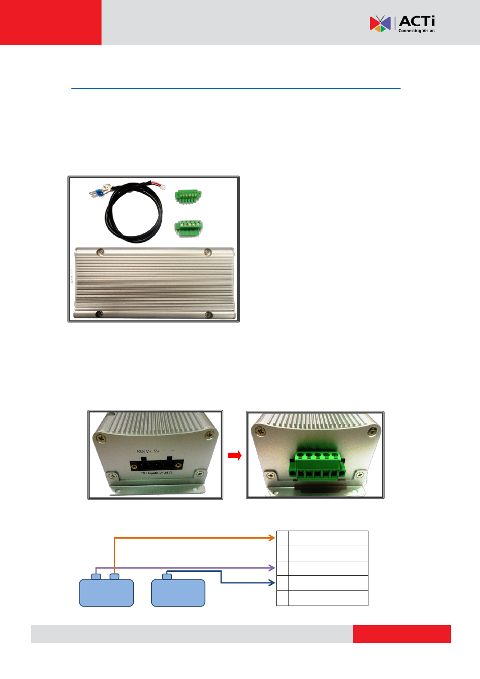
Step 1: Prepare all parts provided for your power ignition control module
Step 2: Prepare a cable to connect your vehicle battery and ignition to the power
ignition control module. Connect the vehicle battery and ignition to the module
’s power
input socket.
Attach and secure the 5-pin block connector to the power ignition control module
’s power input
socket, marked as
“DC Input (9V~36V)”:
Connect the vehicle battery and ignition to the module
’s power input socket by referring to the
wiring definition below:
1 GND
2 GND
3 POWER IN (9V~36V)
4 POWER IN (9V~36V)
5 ACC IN (IGNITION)
Power Ignition Control Module x 1
5-pin Block Connector x1
6-pin Block Connector x1
S3-to-Power Ignition Port Cable x 1
Battery
Ignition