H3C Technologies H3C S12500 Series Switches User Manual
Page 15
Advertising
5
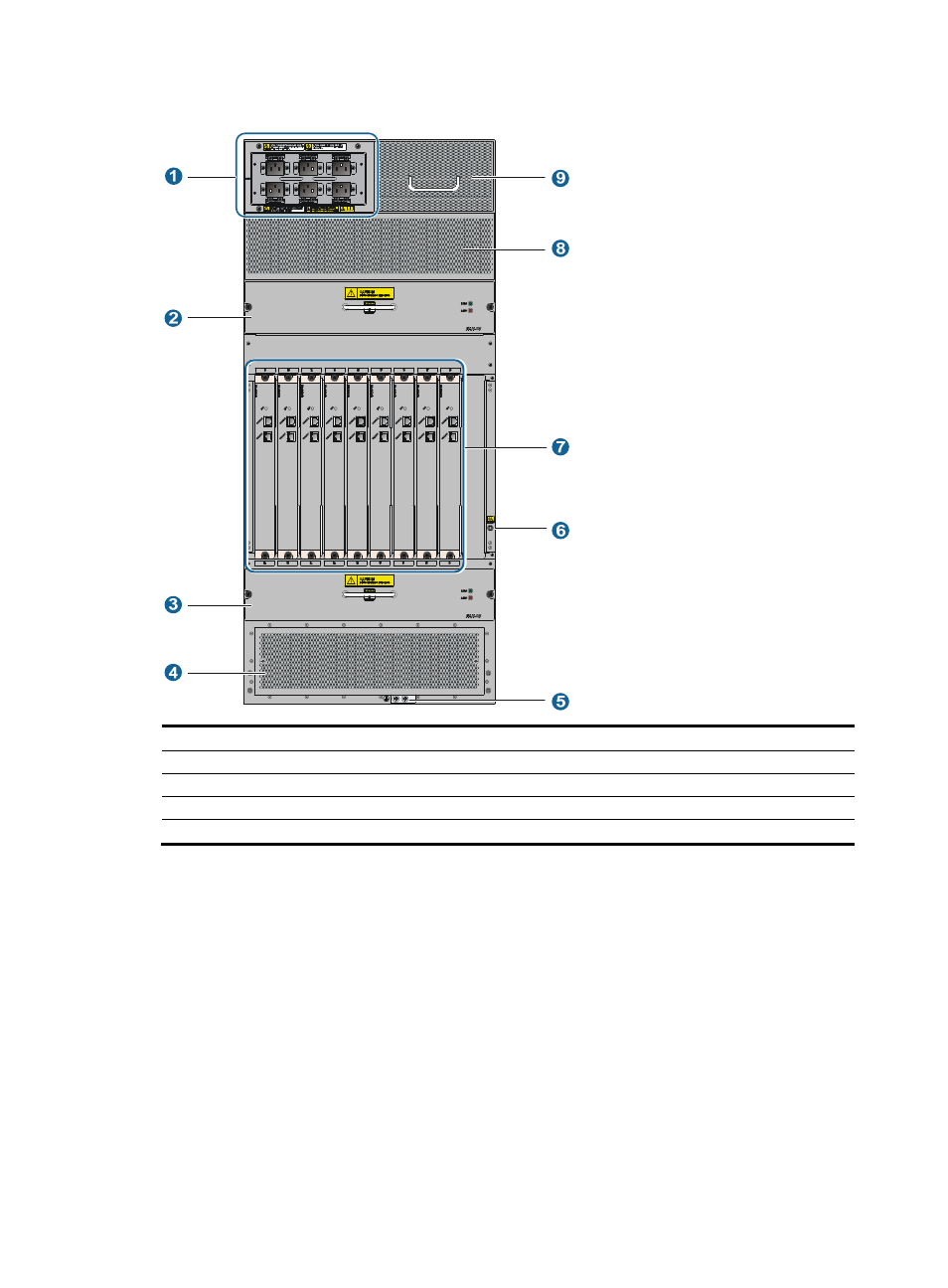
Figure 4 S12508 rear view
(1) Power entry module (PEM)
(2) Upper fan tray
(3) Lower fan tray
(4) Ventilation panel
(5) Grounding screw
(6) ESD-preventive wrist strap port
(7) Switching fabric module slots (slots 10 to 18)
(8) Chassis air exhaust vents
(9) Power supply air exhaust vents
The S12508 chassis has the following slots and components:
•
Two MPU slots and eight LPU slots at the front, and nine switching fabric module slots at the rear.
•
One power frame, at the top of the chassis, can accommodate up to six power supplies.
•
Two horizontally oriented fan trays at the rear of the chassis. For the ventilation direction inside the
chassis, see "Preparing for installation."
Advertising
See also other documents in the category H3C Technologies Routers:
- H3C S12500X-AF Series Switches (3 pages)
- H3C S12500X-AF Series Switches (3 pages)
- H3C S12500X-AF Series Switches (53 pages)
- H3C S12500 Series Switches (19 pages)
- H3C MSV 50 (8 pages)
- H3C S12500 Series Switches (21 pages)
- H3C S9500E Series Switches (4 pages)
- H3C S7500E Series Switches (3 pages)
- H3C WA2200 Series WLAN Access Points (42 pages)
- H3C S12500-X Series Switches (8 pages)
- H3C SR6600 (64 pages)
- H3C S9500E Series Switches (36 pages)
- H3C WA3600 Series Access Points (237 pages)
- H3C S9500E Series Switches (270 pages)
- H3C MSR 900 (249 pages)
- H3C S12500 Series Switches (163 pages)
- H3C MSR 900 (96 pages)
- H3C MSR 900 (443 pages)
- H3C MSR 900 (468 pages)
- H3C S9500E Series Switches (32 pages)
- H3C S9500E Series Switches (241 pages)
- H3C S12500 Series Switches (39 pages)
- H3C S6800 Series Switches (59 pages)
- H3C LSBM1WCM2A0 Access Controller Module (197 pages)
- H3C S10500 Series Switches (27 pages)
- H3C LSBM1WCM2A0 Access Controller Module (226 pages)
- H3C S6300 Series Switches (188 pages)
- H3C MSR 900 (410 pages)
- H3C MSR 900 (239 pages)
- H3C WA3600 Series Access Points (394 pages)
- H3C S10500 Series Switches (2 pages)
- H3C S10500 Series Switches (2 pages)
- H3C S10500 Series Switches (2 pages)
- H3C S10500 Series Switches (2 pages)
- H3C S10500 Series Switches (2 pages)
- H3C S10500 Series Switches (2 pages)
- H3C S10500 Series Switches (2 pages)
- H3C S10500 Series Switches (1 page)
- H3C S7500E Series Switches (19 pages)
- H3C S7500E Series Switches (115 pages)
- H3C S6300 Series Switches (58 pages)
- H3C S6300 Series Switches (208 pages)
- H3C S6300 Series Switches (251 pages)
- H3C S10500 Series Switches (140 pages)