Installation procedure – H3C Technologies H3C S12500 Series Switches User Manual
Page 39
29
IMPORTANT:
•
Make sure no filler panel or card is installed on the front panel of the switch before you remove or install
a lower cable management bracket.
•
Keep the removed chassis panel and cable management brackets for future use.
Installation procedure
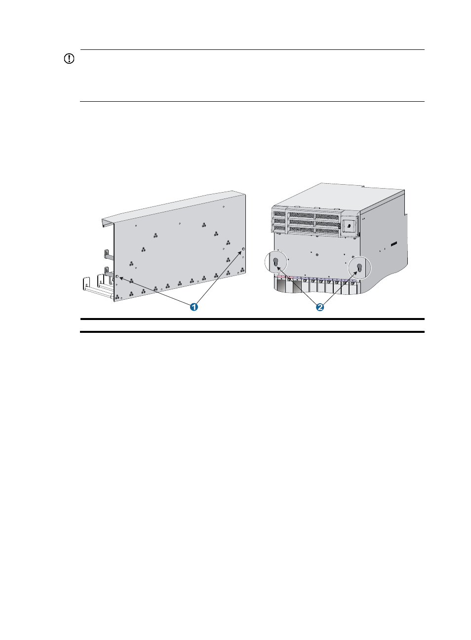
Each S12500 switch has keyhole standoffs on its cable management bracket and keyholes on the chassis
for attaching the cable management bracket to the chassis. See
Figure 27 Keyhole standoff and keyhole
(1) Keyhole standoff
(2) Keyhole
Installing an upper expansion cable management bracket
1.
Holding the notches on both sides of the chassis panel above the upper cable management
bracket, gently remove the panel.
2.
Pressing the two sides of the front panel, pivot the power frame front panel upward.
3.
Loosen the fastening screws on the upper cable management bracket with a Phillips screwdriver.
4.
Align the keyhole standoffs on the rear of the cable management bracket with the keyholes on the
chassis and remove the cable management bracket.
5.
Align the keyhole standoffs on the upper expansion cable management bracket (with a mark) with
the keyholes on the chassis.
6.
Push the expansion cable management bracket forward until it makes close contact with the
chassis. Then pull the expansion cable management bracket downwards a little until the keyhole
standoff fits into the keyhole on the chassis.
7.
Unpack the screws come with the expansion cable management bracket and fasten them with a
Phillips screwdriver to attach the expansion cable management bracket to the chassis.
8.
Close the power frame front panel.