Drive cable assembly, System overview, Status indicators – Grass Valley K2 Solo 3G Client Service Manual v.9.0 User Manual
Page 32: Front panel indicators, Power led, System overview status indicators
Drive cable assembly
The drive cable assembly includes the disk cables and a bracket for mounting drive connectors in
the chassis.
Related Topics
on page 101
System Overview
The K2 Solo 3G system is a PCIe bus-based Windows computer with extensive enhancements to
provide the video disk recorder functionality. This section explains the major architectural blocks.
Status indicators
The following sections describe the visual and audible indicators that communicate the current
operating status and system health of the K2 Solo 3G system.
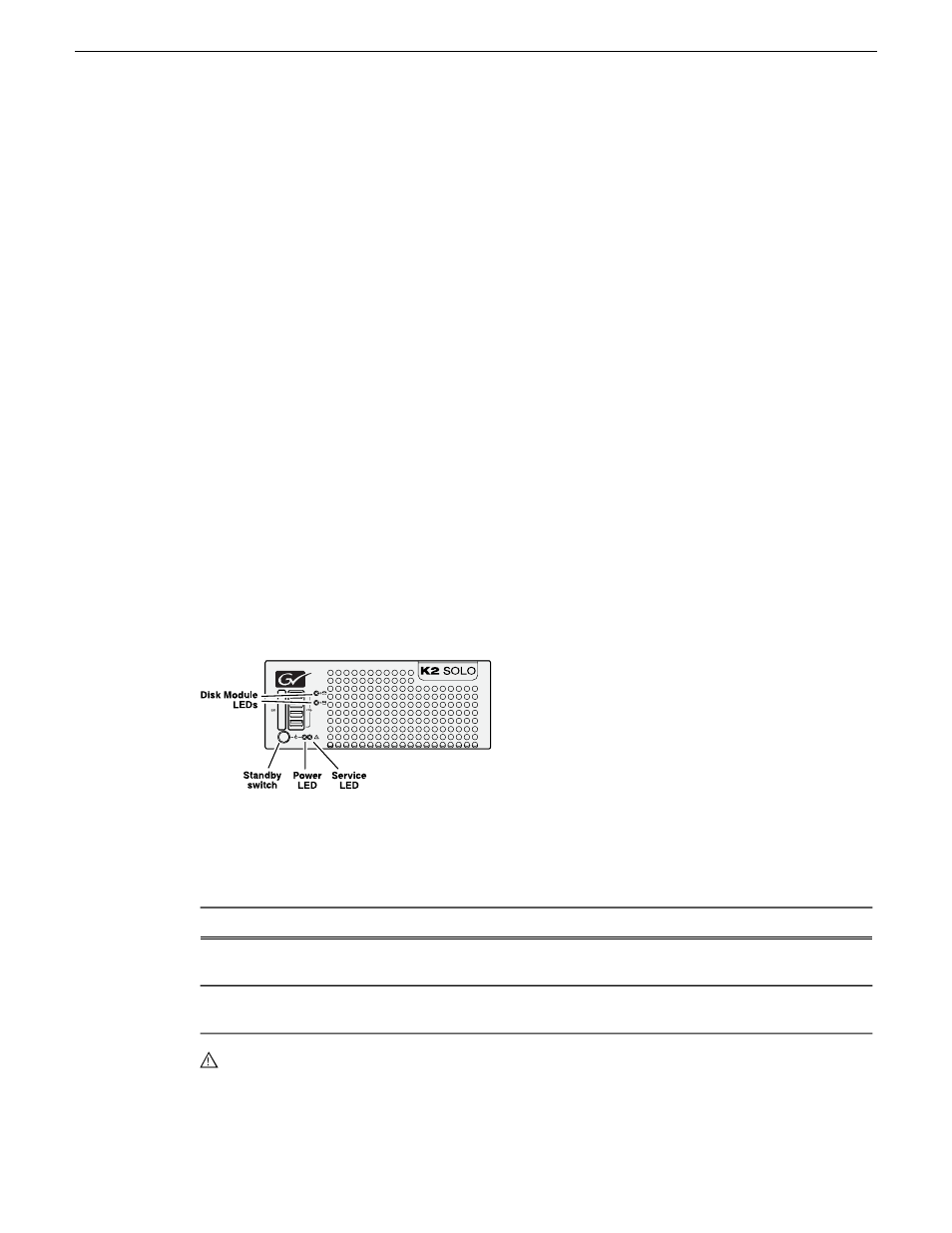
Front panel indicators
The following indicators are visible from the front panel view.
Power LED
The Power LED indicates status as follows::
Status Condition
LED behavior
The standby switch is set to Off and the K2 Solo 3G system is not
operational.
Off
The standby switch is set to On and the K2 Solo 3G system is either in the
startup process or has completed the startup process and is operational.
Green steady on
WARNING: The power standby switch does not turn off power to the system. To turn power off both
power supplies must be disconnected from the power source.
32
K2 Solo 3G Service Manual
06 November 2012
Product description