4 local panel setup – Grass Valley XtenDD v.4.2.4 User Manual
Page 458
4. Setup and Maintenance
4 – 7
Operating Instructions – Rev. 1 / 7.2002
4.4
LOCAL PANEL SETUP
With the setup function you can set system parameters of the switcher panel and
easily change them for a desired configuration.
Control is made via the 16-digit display on the Master TiM/E panel section and the
buttons near by.
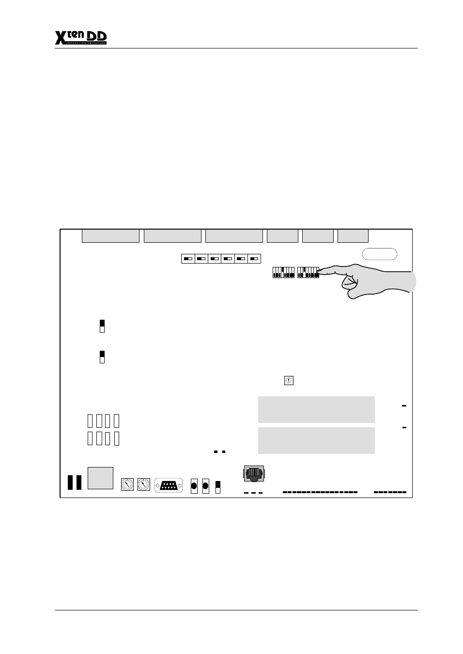
4.4.1
ENABLE THE PANEL SETUP
Enable the panel setup mode by setting the DIL switch T15/3 (RY 2100) or T28/3
(RY 2370) on the panel controller board to ON (upper position) :
Example:
J1
J5
RY 2100
J2
J3
J4
T14
T15
T2
FLASH
T18
EPROM
OPER
T30
FLASH
BATT
OFF
ON
J6
T19
J25 J26 J27
DC
ON/OFF
T3
T4
T5
T6
T7
TEST
RESET
HIGH
DIAGNOSE
PROGR
G3
G18
VCC 4.95V VCC OK VBA
TT
F
AIL
MASTER ERROR
LAN ACC TEMP
F
AIL
PC RESET
SIMM 1
SIMM 2
PC POWER FAIL
LAN ADDRESS
LOW
C
8
9
B
D
E
0
F
A
5
6
2
3
4
7
1
C
8
9
B
D
E
0
F
A
5
6
2
3
4
7
1
T26
T27
J36
T25
R12
G31
G30
1
16
T28
T29
J24
T2
G19
G25
GPI1
GPI2
GPI3
GPI4
GPI5
GPI6
J35
M16 M17
J38 J37
GND
VCC
T
est Socket 5V
VCC GND