Grass Valley XtenDD v.4.2.4 User Manual
Page 476
Advertising
5. Application Notes
5 – 3
Operating Instructions – Rev. 1 / 7.2002
5.1.2
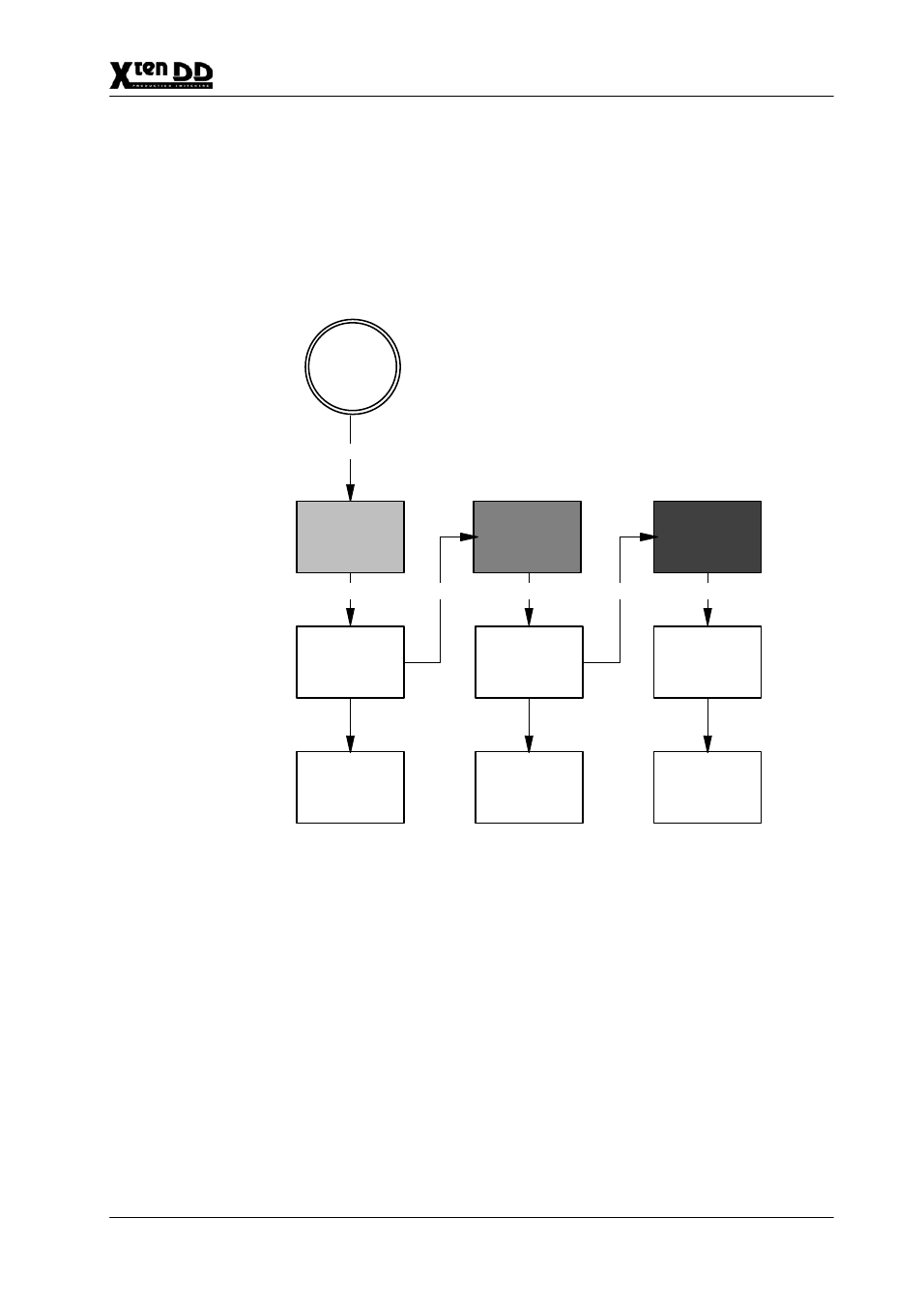
INTERACTION WITH OTHER FUNCTIONS
D
AUX–Couple
When switching a bus to which further busses are coupled, proceeding is as
follows: The original bus is switched via the LAN substitution table to a substi-
tute source. Subsequently this substitute source copies itself with own Aux1
Substitution Table into the coupled busses.
LAN–Msg
PP–PGM–
Source
1
LAN
Substitution
Table
AUX1
Substitution
Table
AUX4
Substitution
Table
2
4
6
3
5
PP–PGM
Source State
AUX1–Source
State
AUX4–Source
State
PP–PGM
Source
Hardware
AUX1–Source
Hardware
AUX4–Source
Hardware
AUX1 coupled to PP/PGM
AUX1 coupled to AUX1
Figure 2
LAN Input Source Substitution & AUX Couple
Advertising