F7 to a1000 terminal comparison, 6 main control pcb comparison – Yaskawa F7 to A1000 User Manual
Page 11
6 Main Control PCB Comparison
YASKAWA PL.A1000.02 F7 to A1000 - Product Transition Guide
11
F7 to A1000 Terminal Comparison
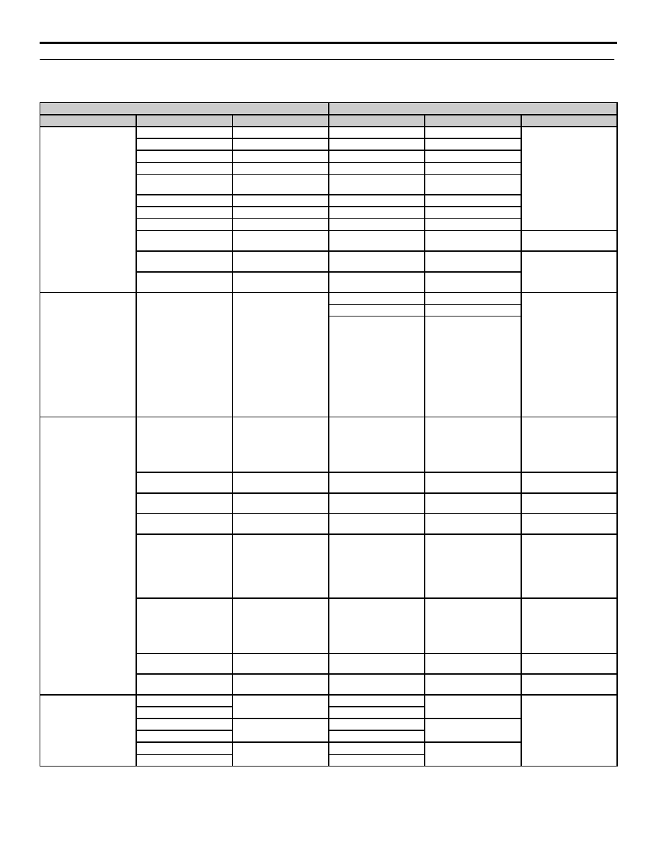
Table 6 Factory Default Terminal Functions 2-Wire Control
F7 Terminal
A1000 Terminal (Designations similar to F7)
Type
F7 Terminal
Default Function
A1000 Terminal
Default Function
A1000 Description
Digital Input Signals
S1
Forward run/stop command
S1
Forward run/stop
Multi-function inputs 1-8
Photocoupler
24 Vdc, 8 mA
Set the S3 jumper to select
between sinking, sourcing
mode, and the power supply.
S2
Reverse run/stop command
S2
Reverse run/stop
S3
External fault input
S3
External fault, N.O.
S4
Fault reset
S4
Fault reset
S5
Multi-step speed reference 1
(Master/auxiliary switch)
S5
Multi-step speed reference 1
S6
Multi-step speed reference 2
S6
Multi-step speed reference 2
S7
Jog frequency reference
S7
Jog reference
S8
External baseblock N.O.
S8
External baseblock
SC
Factory connected to SP
SC
Multi-function input
common
—
SN
Digital input common
SN
Digital input power supply
0 V
24 Vdc power supply for
digital inputs, 150 mA max
(only when not using digital
input option DI-A3)
SP
Factory connected to SC
SP
Digital input power supply
+24 Vdc
Safe Disable Inputs
—
—
H1
Safe Disable input 1
• 24 Vdc, 8mA
• One or both open: Output
disabled
• Both closed: Normal
operation
• Internal impedance: 3.3 kΩ
• Of time of at least 1 ms
Disconnect the wire jumpers
shorting terminals H1, H2,
and HC to use the Safe
Disable inputs. Set the S5
jumper to select between
sinking, sourcing mode, and
the power supply.
H2
Safe Disable input 2
HC
Safe Disable function
common
Analog Input Signals
RP
Pulse input
RP
Multi-function pulse train
input (frequency reference)
Input frequency range: 0 to 32
kHz
Signal Duty Cycle: 30 to 70 %
High level: 3.5 to 13.2 Vdc,
low level: 0.0 to 0.8 Vdc
Input impedance: 3 kΩ
+V
+15 Vdc power output
+V
Power supply for analog
inputs
10.5 Vdc (max allowable
current 20 mA)
-V
-15 Vdc power output
-V
Power supply for analog
inputs
-10.5 Vdc (max allowable
current 20 mA)
A1
Analog input or speed
command
A1
Multi-function analog input
1 (Frequency reference bias)
-10 to 10 Vdc, 0 to 10 Vdc
(input impedance: 20 kΩ)
A2
Add to terminal A1
A2
Multi-function analog input
2 (Frequency reference bias)
-10 to 10 Vdc, 0 to 10 Vdc
(input impedance: 20 kΩ)
4 to 20 mA, 0 to 20 mA (input
impedance: 250 kΩ)
Voltage or current input must
be selected by DIP switch S1
and H3-09.
A3
Aux. frequency reference 1
A3
Multi-function analog input
3 (Auxiliary frequency
reference)/PTC input
-10 to 10 Vdc, 0 to 10 Vdc
(input impedance: 20 kΩ)
Use DIP switch S4 on the
terminal board to select
between analog and PTC
input
AC
Analog common
AC
Analog frequency reference
common
0 V
E(G)
Shield wire, optional ground
line connection point
E(G)
Ground for shielded lines
and option cards
—
Digital Output Signals
M1
During run
(N.O. contact)
M1
During run
(closed at run)
• Multi-function digital
outputs,
• N.O. contacts, 30 Vdc,
10 mA to 1 A
• 250 Vac, 10 mA to 1 A
• Minimum load: 5 Vdc,
10 mA
M2
M2
M3
Zero speed
(N.O. contact)
M3
Zero speed
(closed at zero speed)
M4
M4
M5
Frequency agree
(N.O. contact)
M5
Speed Agree 1
(closed at speed agree)
M6
M6