10 appendix 2 parameter cross reference – Yaskawa F7 to A1000 User Manual
Page 38
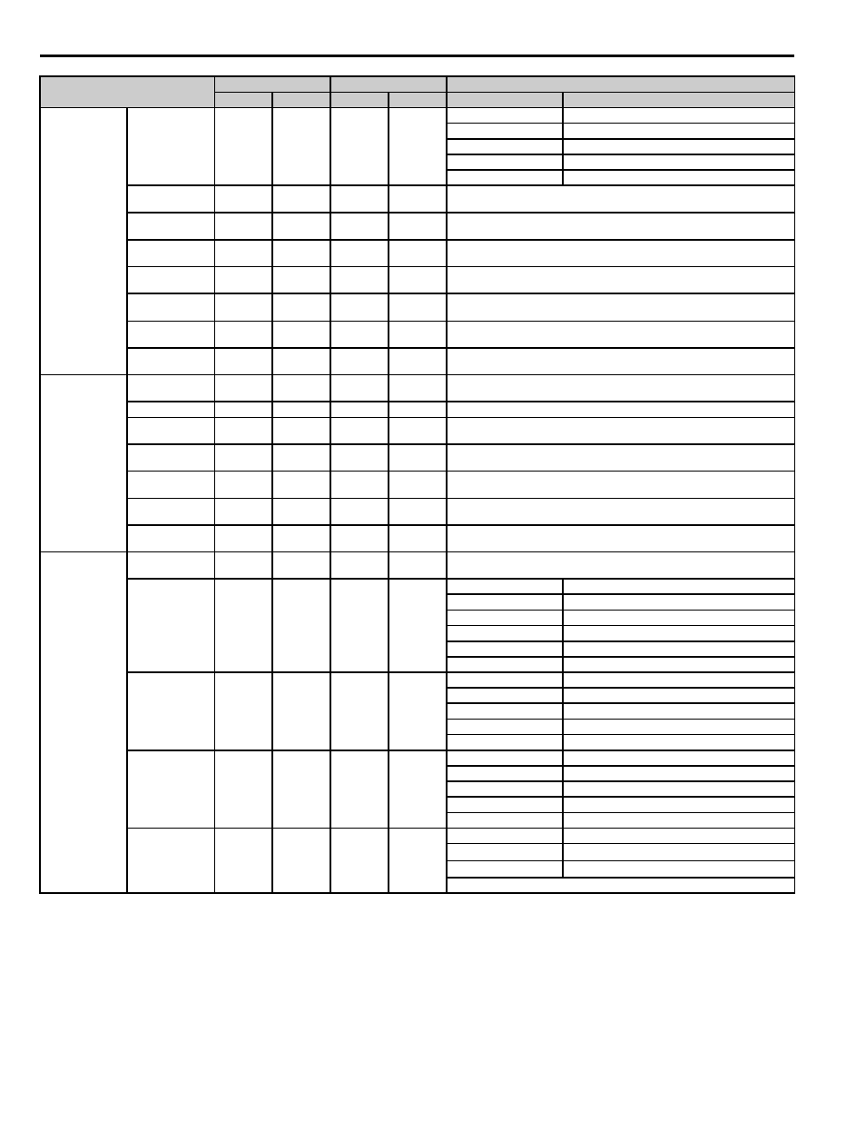
10 Appendix 2 Parameter Cross Reference
38
YASKAWA PL.A1000.02 F7 to A1000 - Product Transition Guide
Motor 2 V/f
Characteristics
Motor 2 Control
Method Selection
E3-01
2
E3-01
0
E3-01
E3-01
0: V/f
0: V/f
1: V/f w/PG
1: V/f w/PG
2: Open Loop Vector
2: Open Loop Vector
3: Flux Vector Control
3: Closed Loop Vector
Motor 2 Max
Output Frequency
E3-02
60.0 Hz
E3-04
*
*Dependent on E3-01 and control method selected
Motor 2 Max
Voltage
E3-03
230 V or
460 V
*
E3-05
*
*Dependent on E3-01 and control method selected
Double values for 400 V class drives
Motor 2 Base
Frequency
E3-04
60.0 Hz
E3-06
*
*Dependent on E3-01 and control method selected
Motor 2 Mid.
Output Frequency
E3-05
3.0 Hz
E3-07
*
*Dependent on E3-01 and control method selected
Motor 2 Mid.
Output Voltage VA
E3-06
12.6 V or
25.3 V
*
E3-08
*
*Dependent on E3-01 and control method selected
Double values for 400 V class drives
Motor 2 Minimum
Output Frequency
E3-07
0.5 Hz
E3-09
*
*Dependent on E3-01 and control method selected
Motor 2 Minimum
Output Voltage
E3-08
2.3 V or
4.6 V
E3-10
*
*Dependent on E3-01 and control method selected
Double values for 400 V class drives
Motor 2 Parameter
Motor 2 Rated
Current
E4-01
*
E4-01
*
*Varies by kVA; A1000 dependent on C6-01 and o2-04
Motor 2 Rated Slip
E4-02
*
E4-02
*
*Varies by kVA; A1000 dependent on C6-01 and o2-04
Motor 2 No-Load
Current
E4-03
*
E4-03
*
*Varies by kVA; A1000 dependent on C6-01 and o2-04
Motor 2 Number of
Poles
E4-04
4 E4-04
4
—
Motor 2 Line-to-
Line Resistance
E4-05
*
E4-05
*
*Varies by kVA; A1000 dependent on C6-01 and o2-04
Motor 2 Leakage
Inductance
E4-06
*
E4-06
*
*Varies by kVA; A1000 dependent on C6-01 and o2-04
Motor 2 Rated
Output
E4-07
*
E4-11
*
*Varies by kVA; A1000 dependent on C6-01 and o2-04
PG speed Control
Card
PG 1 Pulses Per
Revolution
F1-01
1024
F1-01
1024
—
Operation
Selection at PG
Open Circuit
(PGO)
F1-02
1
F1-02
1
F1-02
F1-02
0: Ramp to stop
0: Ramp to stop
1: Coast to stop
1: Coast to stop
2: Fast Stop
2: Fast Stop
3: Alarm Only
3: Alarm Only
—
4: No Alarm Display
Operation
Selection at
Overspeed (OS)
F1-03
1
F1-03
1
F1-03
F1-03
0: Ramp to stop
0: Ramp to stop
1: Coast to stop
1: Coast to stop
2: Fast Stop
2: Fast Stop
3: Alarm Only
3: Alarm Only
Operation
Selection at
Deviation
F1-04
3
F1-04
3
F1-04
F1-04
0: Ramp to stop
0: Ramp to stop
1: Coast to stop
1: Coast to stop
2: Fast Stop
2: Fast Stop
3: Alarm Only
3: Alarm Only
PG 1 Rotation
Selection
F1-05
0
F1-05
0*
F1-05
F1-05
0:
FWD = Phase A leads
0:
FWD = Phase A leads
1:
FWD = Phase B leads
1:
FWD = Phase B leads
*Determined by parameter A1-02
Parameter Name
F7
A1000
Setting
Parameter
Default
Parameter
Default
F7
A1000