10 appendix 2 parameter cross reference – Yaskawa F7 to A1000 User Manual
Page 37
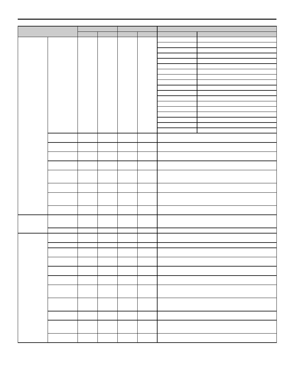
10 Appendix 2 Parameter Cross Reference
YASKAWA PL.A1000.02 F7 to A1000 - Product Transition Guide
37
V/f Characteristics
V/f Pattern
Selection
E1-03
F
E1-03
F
E1-03
E1-03
0: 50 Hz
0: 50 Hz (constant torque 1)
1: 60 Hz saturation
1: 60 Hz (constant torque 2)
2: 50 Hz saturation
2: 60 Hz (constant torque 3), 50 Hz base
3: 72 Hz, 60 Hz base
3: 72 Hz (constant torque 4), 60 Hz base
4: 50 Hz VT1
4: 50 Hz VT1
5: 50 Hz VT2
5: 50 Hz VT2
6: 60 Hz VT1
6: 60 Hz VT3
7: 60 Hz VT2
7: 60 Hz VT4
8: 50 Hz HST1
8: 50 Hz HST1
9: 50 Hz HST2
9: 50 Hz HST2
A: 60 Hz HST1
A: 60 Hz HST3
B: 60 Hz HST2
B: 60 Hz HST4
C: 90 Hz (60 Hz base)
C: 90 Hz (60 Hz base)
D: 120 Hz (60 Hz base)
D: 120 Hz (60 Hz base)
E: 180 Hz (60 Hz base)
E: 180 Hz (60 Hz base)
F: Custom V/f pattern
F: Custom V/f pattern
FF: Custom w/o limit
—
Max Output
Frequency
E1-04
60.0 Hz
E1-04
60.0 Hz
*
*Depends on the parameters A1-02, C6-01, o2-04, and E5-01
Max Voltage
E1-05
230.0 V
*
E1-05
*
*Double values for 400 V class drives. Depends on the parameters A1-02, C6-01, o2-
04, and E5-01
Base Frequency
E1-06
60.0 Hz
*
E1-06
*
*Depends on the control mode and the V/f pattern selected. Depends on the
parameters A1-02, C6-01, o2-04, and E5-01
Mid. Output
Frequency
E1-07
3.0 Hz
*
E1-07
3.0 Hz
*Depends on the control mode and the V/f pattern selected. Depends on the
parameters A1-02, C6-01, and o2-04
Mid. Output
Frequency Voltage
E1-08
12.6 V or
25.3 V
*
E1-08
*
*Depends on the control mode and the V/f pattern selected.
Double values for 400 V class drives. Depends on the parameters A1-02, C6-01, and
o2-04 in A1000 drives
Minimum Output
Frequency
E1-09
0.5 Hz
*
E1-09
*
*Depends on the control mode and the V/f pattern selected. Depends on the
parameters A1-02, C6-01, o2-04, and E5-01
Minimum Output
Frequency Voltage
E1-10
2.3 V or 4.6
V
*
E1-10
*
*Depends on the control mode and the V/f pattern selected.
Double values for 400 V class drives. Depends on the parameters A1-02, C6-01, and
o2-04
Mid. Output
Frequency 2
E1-11
0.0 Hz
E1-11
0.0 Hz
—
V/f Characteristic
Mid. Output
Frequency Voltage
2
E1-12
0.0 V
E1-12
0.0 V
—
Base Voltage
E1-13
0.0 V
E1-13
0.0 V
—
Motor Parameters
Motor Rated
Current
E2-01
*
E2-01
*
—
Motor Rated Slip
E2-02
*
E2-02
*
*Varies by kVA; for A1000, dependent on parameters C6-01 and o2-04
Motor No-Load
Current
E2-03
*
E2-03
*
*Varies by kVA; for A1000, dependent on parameters C6-01 and o2-04
Number of Motor
Poles
E2-04
4 poles
E2-04
4 poles
—
Motor Line-to-
Line Resistance
E2-05
*
E2-05
*
*Varies by kVA; for A1000, dependent on parameters C6-01 and o2-04
Motor Leakage
Inductance
E2-06
*
E2-06
*
*Varies by kVA; for A1000, dependent on parameters C6-01 and o2-04
Motor Iron Core
Saturation Co-
Efficient 1
E2-07
0.50
E2-07
0.50
—
Motor Iron Core
Saturation Co-
Efficient 2
E2-08
0.75
E2-08
0.75
—
Motor Mechanical
Loss
E2-09
0.0 %
E2-09
0.0 %
—
Motor Iron Loss
for Torque
Compensation
E2-10
*
E2-10
*
*Varies by kVA; for A1000, dependent on parameters C6-01 and o2-04
Motor Rated
Output
E2-11
*
E2-11
*
*Varies by kVA; for A1000, dependent on parameters C6-01 and o2-04
Parameter Name
F7
A1000
Setting
Parameter
Default
Parameter
Default
F7
A1000