Yaskawa GPD 506/P5 to F7 User Manual
Page 15
Product Transition Guide
GPD506/P5 to F7
PL.F7.05 Page
15
of 54
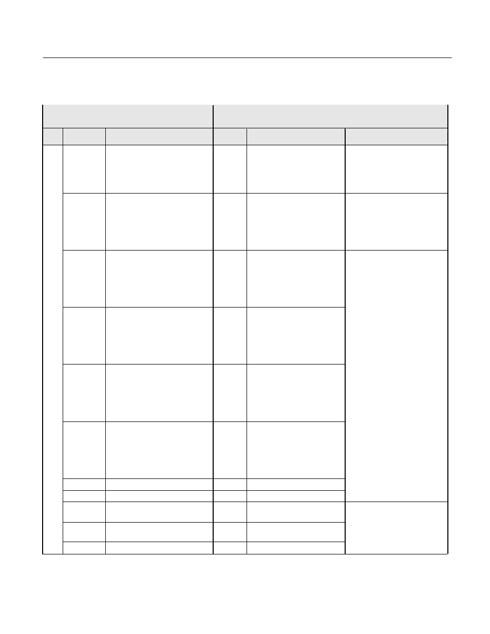
GPD506/P5 to F7 Terminal Comparison
The factory default is 2-wire control as shown.
GPD506/P5 Terminal
F7 Terminal
(Designations similar to GPD506/P5)
Type
GPD506/P5
Terminal
Default Function & Description
F7
Terminal
Default Function
F7 Description
S1
Forward run/stop, Forward run
when closed, and stop when
open.
Photo-coupler insulation
Input: +24VDC 8mA
S1
Forward run/stop command
–
S2
Reverse run/stop, Reverse run
when closed, Stop when open.
Multi-function contact
input (n036)
Photo-coupler insulation
Input: +24VDC 8mA
S2
Reverse run/stop command
–
S3
External fault input, Fault when
closed, normal state when open.
Multi-function contact input
(n037)
Photo-coupler insulation
Input: +24VDC 8mA
S3
External fault input
S4
Fault reset input,
Reset when closed.
Multi-function contact input
(n038)
Photo-coupler insulation
Input: +24VDC 8mA
S4
Fault reset
S5
Multi-step speed reference 1,
Enabled when closed.
Multi-function contact input
(n039)
Photo-coupler insulation
Input: +24VDC 8mA
S5
Multi-step speed reference 1
(Master/auxiliary switch)
S6
Multi-step speed reference 2,
Enabled when closed.
Multi-function contact input
(n040)
Photo-coupler insulation
Input: +24VDC 8mA
S6
Multi-step speed reference 2
–
–
S7
Jog frequency reference
–
–
S8
External baseblock N.O.
Multi-function digital inputs.
Functions set by:
H1-01 to H1-06.
24 VDC, 8mA
Photo coupler isolation
SC
Sequence input common
terminal
SN
Digital input common
–
SC
Factory connected to SP
Di
gi
ta
l Input
Si
gnal
s
–
SP
Factory connected to SC
Factory connected for internal
supply sinking mode.
Refer to F7 User Manual for
other methods.