Appendix 3- parameter cross reference, Parameter name – Yaskawa GPD 506/P5 to F7 User Manual
Page 50
Appendix 3- Parameter Cross Reference
PL.F7.05 Page
50
of 54
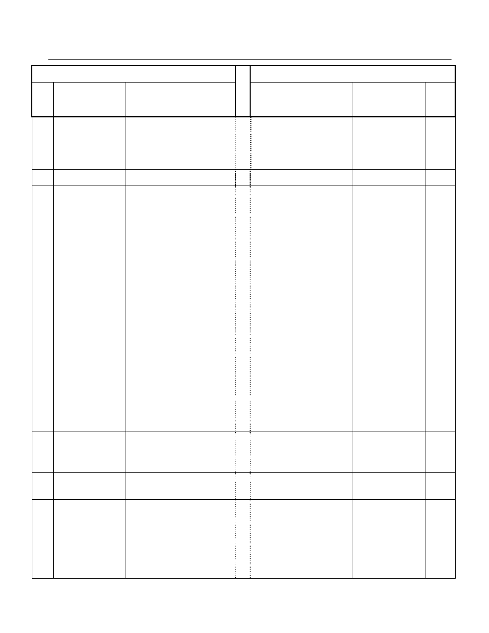
GPD506/P5 Parameter
F7 Parameter
Param
No.
Nxxx
Parameter
Name
Description or Selection
Description or Selection
Parameter
Name
Param.
No.
075
Set frequency
detection level
Set unit: 0.1Hz and set range: 0.0-400.0Hz
0.0 to 400.0
These parameters configure the multi-
function output (H2-
)
settings “Fref/Fout agree 1”, “Fref/Set
agree 1”, “Frequency detection 1,” and
“Frequency detection 2". They are used as
a setpoint and hysteresis for a contact
closure for the functions.
Speed Agreement Detection
Level
L4-01
076
Width of frequency
agreement detection
Set unit: 0.1Hz and set range: 0.0-25.5Hz
0.0 to 20.0
Speed Agreement Detection
Width
L4-02
077
Overtorque/
Undertorque
Selection
0: Overtorque/undertorque detection disabled.
1: Overtorque is detected during constant
speed operation and operation continues
after overtorque detection.
2: Overtorque is always detected and
operation continues after overtorque
detection.
3: Overtorque is detected during constant
speed operation and inverter output is
disabled after overtorque detection.
4: Overtorque is always detected and inverter
output is disabled after overtorque detection.
5: Undertorque is detected during constant
speed operation and operation continues
after undertorque detection.
6: Undertorque is always detected and
operation continues after undertorque
detection.
7: Undertorque is detected during constant
speed operation and inverter output is
disabled after undertorque detection.
8: Undertorque is always detected and inverter
output is disabled after undertorque
detection.
Determines the Drive's response to an
Overtorque/Undertorque condition.
Overtorque and Undertorque are
determined by the settings in parameters
L6-02 and L6-03. The multi-function
output settings “B” and “17” in the H2-
parameter group are also active if
programmed.
0: Disabled
1: OL3 at Speed Agree - Alarm
(Overtorque Detection only active during
Speed Agree and Operation continues
after detection).
2: OL3 at RUN - Alarm (Overtorque
Detection is always active and operation
continues after detection).
3: OL3 at Speed Agree - Fault (Overtorque
Detection only active during Speed
Agree and Drive output will shut down
on an OL3 fault).
4: OL3 at RUN - Fault (Overtorque
Detection is always active and Drive
output will shut down on an OL3 fault).
5: UL3 at Speed Agree – Alarm
(Undertorque Detection is only active
during Speed Agree and operation
continues after detection).
6: UL3 at RUN - Alarm (Undertorque
Detection is always active and operation
continues after detection).
7: UL3 at Speed Agree – Fault
(Undertorque Detection only active
during Speed Agree and Drive output
will shut down on an OL3 fault).
8: UL3 at RUN - Fault (Undertorque
Detection is always active and Drive
output will shut down on an OL3 fault).
Torque Detection Selection 1
L6-01
078
Overtorque detection
level
Set unit: 1%
Set range: 30-200%
(100%= rated current of inverter)
0 to 300
Sets the Overtorque/Undertorque detection
level as a percentage of Drive rated current
or torque for torque detection 1. Current
detection for A1-02 = 0 or 1. Torque
detection for A1-02 = 2 or 3.
Torque Detection Level 1
L6-02
079
Overtorque detection time
Set unit: 0.1sec and set range: 0.1-10.0sec
0.0 to 10.0
Sets the length of time an Over/Under
torque condition must exist before torque
detection 1 recognized by the Drive.
Torque Detection Time 1
L6-03
080
(timer function)
ON Delay time
Set unit: 0.1sec
Set range: 0.0-25.5sec
0.0 to 3000.0
Used in conjunction with a multi-function
digital input and a multi-function digital
output programmed for the timer function.
This sets the amount of time between when
the digital input is closed, and the digital
output is energized.
Timer Function ON-Delay
Time
b4-01