Appendix 3- parameter cross reference, Parameter name, Description or selection – Yaskawa GPD 506/P5 to F7 User Manual
Page 38
Appendix 3- Parameter Cross Reference
PL.F7.05 Page
38
of 54
GPD506/P5 Parameter
F7 Parameter
Param
No.
Nxxx
Parameter
Name
Description or Selection
Description or Selection
Parameter
Name
Param.
No.
S-Curve Characteristic at
Decel End
C2-04
023
Digital operator
display mode
Set range: 0-4999
0: Hz with 0.1Hz
1: % speed with 0.1%
2-39: RPM. RPM =120 * freq ref(Hz) /n023
(N023 is a motor pole)
40-4999:
n23 fourth digit = decimal point
n23 1,2,3 digits = 100% freq set value
(100% frequency = xxx*10 in case of 4xxx)
Digital Operator Display
Selection
o1-03
024
Freq Ref 1
Set unit: Set range by constant n023 setting:
0-9999
0.00 to E1-04 Value
Setting units are affected by o1-03
Frequency Reference 1
d1-01
025
Freq Ref 2
Set unit: Set range by constant n023 setting:
0-9999
0.00 to E1-04 Value
Frequency reference when multi-function
input “Multi-step speed reference 1” is ON.
Setting units are affected by o1-03.
Frequency Reference 2
d1-02
026
Freq Ref 3
Set unit: Set range by constant n023 setting:
0-9999
0.00 to E1-04 Value
Frequency reference when multi-function
input “Multi-step speed reference 2” is ON.
Setting units are affected by o1-03.
Frequency Reference 3
d1-03
027
Freq Ref 4
Set unit: Set range by constant n023 setting:
0-9999
0.00 to E1-04 Value
Frequency reference when multi-function
input “Multi-step speed reference 1,2” is
ON. Setting units are affected by o1-03.
Frequency Reference 4
d1-04
028
Freq Ref 5
Set unit: Set range by constant n023 setting:
0-9999 (GPD506 only)
0.00 to E1-04 Value
Frequency reference when multi-function
input “Multi-step speed reference 3” is ON.
Setting units are affected by o1-03.
Frequency Reference 5
d1-05
029
Freq Ref 6
Set unit: Set range by constant n023 setting:
0-9999 (GPD506 only)
0.00 to E1-04 Value
Frequency reference when multi-function
input “Multi-step speed reference 1,3” is
ON. Setting units are affected by o1-03.
Frequency Reference 6
d1-06
030
Jog Ref
Set unit: Set range by constant n023 setting:
0-9999
0.00 to E1-04 Value
Frequency reference when:
“Jog frequency reference” is selected via
multi-function input
terminals. “Jog frequency reference” has
priority over “multi-step speed reference 1
to 4”. d1-17 is also the reference for the
JOG key on the Digital Operator, and the
multi-function inputs “forward jog” and
“reverse jog”. Setting units are affected by
o1-03.
Jog Frequency Reference
d1-17
031
Output freq upper
limit
Set unit: 1% and set range:0-109%
0.0 to 110.0
Determines maximum frequency reference,
set as a percentage of maximum output
frequency (E1-04). If the frequency
reference is above this value, actual Drive
speed will be limited to this value. This
parameter applies to all frequency
reference sources.
Frequency Reference Upper
Limit
d2-01
032
Output freq lower
limit
Set unit: 1% and set range:0-100%
0.0 to 110.0
Determines minimum frequency reference,
set as a percentage of maximum output
frequency (E1-04). If frequency reference
is below this value, actual Drive speed will
be set to this value. This parameter applies
Frequency Reference Lower
Limit
d2-02
Sets the units of the Frequency References (d1-01 to
d1-17), the Frequency Reference Monitors (U1-01,
U1-02, U1-05), and the Modbus communication
frequency reference.
0: Hz
1: % (100% = E1-04)
2 to 39: RPM (Enter the number of motorpoles).
40 to 39999: User display.
Set the number desired at maximum
output frequency.
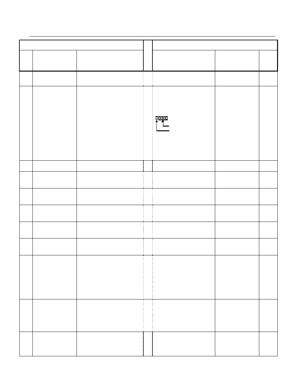
4 digit number
Number of digits from the right of the
decimal point
Example 1: o1-03 = 12000, will result in frequency
reference from 0.0 to 200.0 (200.0 = Fmax).
Example 2: o1-03 = 21234, will result in frequency
reference from 0.00 to 12.34 (12.34 = Fmax).