Appendix 3- parameter cross reference, Parameter name – Yaskawa GPD 506/P5 to F7 User Manual
Page 48
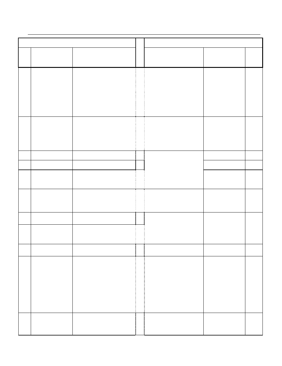
Appendix 3- Parameter Cross Reference
PL.F7.05 Page
48
of 54
GPD506/P5 Parameter
F7 Parameter
Param
No.
Nxxx
Parameter
Name
Description or Selection
Description or Selection
Parameter
Name
Param.
No.
060
No. of Fault Retries
Setting unit = 1 times
Set range: 0-10 times
(There is no fault retry at 0)
0 to 10
Sets the counter for the number of times the
Drive will perform an automatic restart on
the following faults: GF, LF, OC, OV, PF,
PUF, RH, RR, OL1, OL2, OL3, OL4,
UV1. Auto restart will check to see if the
fault has cleared every 5ms. When no fault
is present, the Drive will attempt an auto
restart. If the Drive faults after an auto
restart attempt, the counter is incremented.
When the drive operates without fault for
10 minutes, the counter will reset to the
value set in L5-01
Number of Auto Restart
Attempts
L5-01
061
Fault contact during
fault retry
0: Fault contact output enabled while fault
retry.
1: Fault contact output disabled while fault
retry.
Determines if the fault contact activates
during an automatic restart attempt.
0: No Fault Relay - fault contact will not
activate during an automatic restart
attempt.
1: Fault Relay Active - fault contact will
activate during an automatic restart
attempt.
Auto Restart Operation
Selection
L5-02
062
Jump frequency 1
Set unit: 0.1Hz and set range: 0.0-400.0Hz
Jump Frequency 1
d3-01
063
Jump frequency 2
Set unit: 0.1Hz and set range: 0.0-400.0Hz
Jump Frequency 2
d3-02
064
Width of jump
Set unit: 0.1Hz and set range: 0.0-25.5Hz
0.0 to 200.0
These parameters allow programming of up
to three prohibited frequency reference
points for eliminating problems with
resonant vibration of the motor / machine.
This feature does not actually eliminate the
selected frequency values, but will
accelerate and decelerate the motor through
the prohibited bandwidth.
Jump Frequency Width
d3-04
065
Elapsed timer 1
mode
0: Operation time accumulates.
1: Operation time accumulates. (During Run)
Sets how time is accumulated for the
elapsed operation timer U1-13.
0: Power-On Time - Time accumulates
when the Drive is powered.
1: Running Time - Time accumulates only
when the Drive is running.
Cumulative Operation Time
Selection
o2-08
066
Elapsed timer 1
(lower 4 digits)
Setting unit = 1 hour, range = 0 ~ 9999 hours
1 minute is stored in EEPROM, < 1day
rounded up
067
Elapsed timer 1
(upper 4 digits)
Set unit: 1(For 10000 hours) and a set range:
0-27.
* Initial value becomes 0 only when
initialized during
CPF4 occurrence.
0 to 65535
Sets the initial value of the elapsed
operation timer U1-13.
Cumulative Operation Time
Setting
o2-07
068
DC injection braking current Set unit: 1%
Set range: 0-100%
(100%= rated current of inverter)
0 to 100
Sets the DC injection braking current as a
percentage of the Drive rated current.
DC Injection Braking Current
b2-02
069
DC braking time at stop
Set unit:0.1sec and set range: 0.0-10.0sec
0.00 to 10.00
Sets the time length of DC injection
braking at stop in units of 0.01 seconds.
NOTE: When b1-03 = 2, actual DC
Injection time is calculated as follows:
b2-04 * 10 * Output Frequency / E1-04.
NOTE: When b1-03 = 0, this parameter
determines the amount of time DC
Injection is applied to the motor at the end
of the decel ramp.
NOTE: This should be set to a minimum of
0.50 seconds when using HSB. This will
activate DC injection during the final
portion of HSB and help ensure that the
motor stops completely.
DC Injection Braking Time at
Stop
b2-04
070
DC braking time at start
Set unit: 0.1sec and set range: 0.0-10.0sec
0.00 to 10.00
Sets the time of DC injection braking at
start in units of 0.01 seconds.
DC Injection Braking Time at
Start
b2-03