2 connection diagram, Connection diagram with drive – Yaskawa RC5 Converter User Manual
Page 25
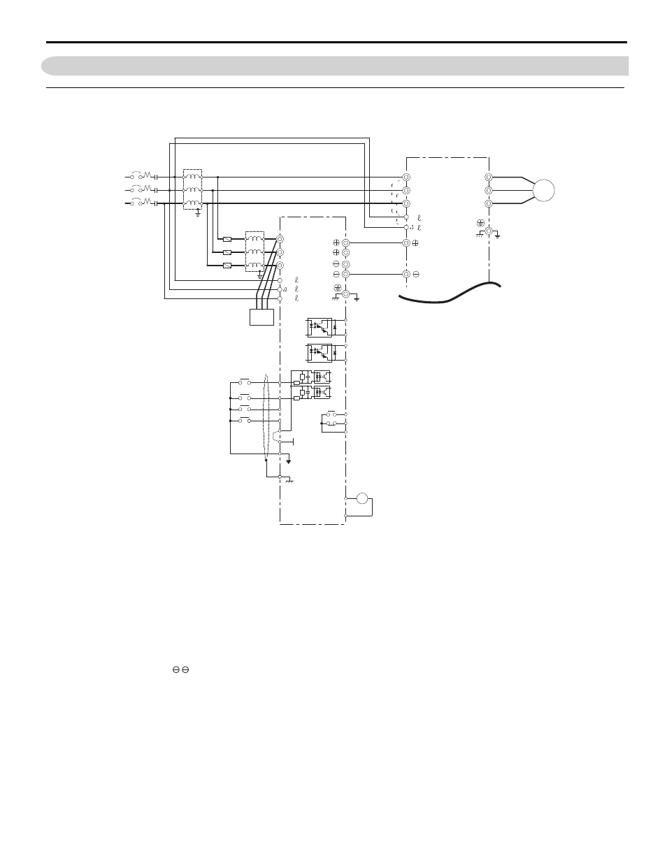
3.2 Connection Diagram
YASKAWA ELECTRIC TOEP C710656 01C YASKAWA - RC5 Instruction Manual
25
3.2
Connection Diagram
◆
Connection Diagram with Drive
shows a diagram of a typical connection of the RC5 with the Yaskawa AC Drive.
Note: The RC5 is compatible with other Yaskawa drive (inverter) products. Refer to the application technical manual for the equivalent connection diagram.
Figure 3.1
Figure 3.1 Connection Diagram (When connecting a RC5 and a Yaskawa AC Drive)
<1> Connect to the terminal (+)1 for 200 V class 0.4 to 22 kW, and 400 V class 0.4 to 45 kW Yaskawa AC drive. Use terminal (+)3 for 200 V class
30 to 37 kW, and 400 V class 55 to 75 kW VS-616G5 drivers or another Yaskawa drive (inverter) product.
<2> Connect the Yaskawa AC Drive power supply terminals R/L1, S/L2, and T/L3 to the secondary side of the power coordinating reactor. Connect
the RC5 AC power supply terminals R/L1, S/L2, and T/L3 to the secondary side of the power suppressing reactor.
<3> Connect terminals r/
l 1, s/l 2 of VS-616G5, and terminals r1/l 11, s 1/l 21, and t1/l 31 of the RC5 to the primary side of the power coordinating
reactor.
<4> Make sure to use the specified reactor, fuse and fuse holder.
<5> The sequence input terminal of RC5 is the same as terminal S1.
<6> The wiring distance between the power coordinating reactor, and RC5 and a Yaskawa AC Drive should be 10 m or less.
<7> DC bus wiring [(+) 1 - (+), ] between the Drive and the power regenerative unit should be 5 m or less.
<8> Remove the wiring of terminals r/
l 1 and s/l 2 since they were connected at the factory.
<9> If installing a circuit breaker or a magnetic contactor on the RC5 output (DC) side to shut down the power supply in an emergency, observe the
following precautions.
• Be sure to confirm that the charge lamps on the RC5 and the Inverter are not lit, and then turn on the circuit breaker or contactor. If the circuit
breaker or contactor is turned on while power is supplied to the RC5 and the Inverter, an overcurrent may occur and damage the circuit breaker or
contactor.
• Be sure to confirm that the circuit breaker or contactor is turned on before the power is turned on for the RC5.
Suppression
Reactor
<3>
<3>
+24V
S1
S2
S3
S4
SS
SP
SC
AUTO RUN
EXFLT
MANUAL RUN
M1
M2
M3
M4
MB
MC
MA
R/L1
S/L2
T/L3
R/L1
S/L2
T/L3
1
E
U/T1
V/T2
W/T3
IM
AC
AM
Running
CONV
READY
-10 to +10V
VS-656RC5
Yaskawa AC Drive
RESET
r1/
11
t1/
31
r/ 1
1/
21
/ 2
MCCB
MC
FU
Power Coordination Reactor
<4>
<4>
<4>
<2>
<5>
<2>
<1>
Current
Sequence
Common
Shield Sheath
Connection Terminal
Analog Output
<6>
<8>
<9>
MOV