Yaskawa RC5 Converter User Manual
Page 60
60
YASKAWA ELECTRIC TOEP C710656 01C YASKAWA - RC5 Instruction Manual
shows the items that can be monitored in operation mode. The output signal levels for multi-function analog outputs shown in the table are
for a gain of 100.0 and a bias of 0.00.
Table A.1 Parameters Monitored in Operation Mode
Function Parameter
No.
Parameter Name /
Display
Function
Output Signal Level for
Multi-function Analog
Outputs
Min.
Unit
Status
Monitor
U1-02
DC bus voltage
Monitors the DC voltage of the power regenerative unit’s internal
main circuit
200 V class: 400 V/10 V
400 V class: 800 V/10 V
(0 to +10 V Output)
1 V
DC Bus Voltage
U1-04
AC power supply voltage
Monitors the AC power supply voltage.
200 V class: 200 V/5 V
400 V class: 400 V/5 V
(0 to +10 V Output)
1 V
AC Voltage
U1-05
Current at power side
Monitors the AC power supply current.
Rated current /10 V
(0 to +10 V Output)
1 A
AC Current
U1-07
Power at power side
Monitors the AC power supply power.
Rated power /10 V
(0 to +10 V Output)
1 kW
AC Power
U1-08
AC power supply frequency
Monitors the AC power supply frequency.
60 Hz /10 V
(0 to +10 V Output)
0.01 Hz
AC Frequency
U1-10
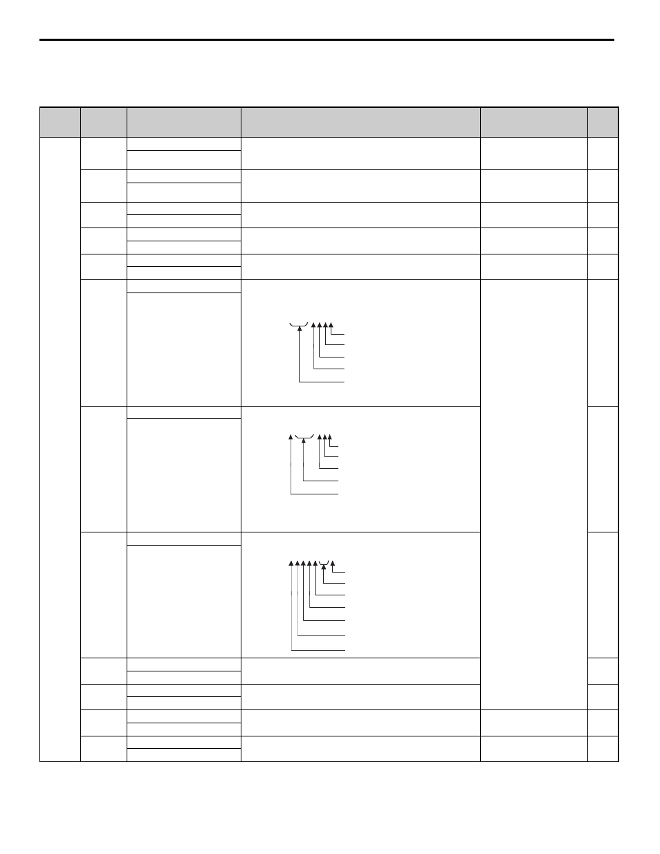
Input terminal status
Shows input ON/OFF status.
(Cannot be output)
—
Input Term Sts
U1-11
Output terminal status
Shows output ON/OFF status.
—
Output Term Sts
U1-12
Operation status
Power regenerative unit operating status.
—
Int Ct1 Sts 1
U1-13
Cumulative operation time
Monitors the power regenerative unit’s elapsed operating time.
Can be set with uparameter o2-07 or o2-08.
—
Elapsed Time
U1-14
Software No.
(Manufacturer’s ID number)
—
FLASH ID
U1-21
Voltage deviation
Monitors the deviation between the AC power supply voltage and
the main circuit DC voltage.
200 V class: 400 V/10 V
400 V class: 800 V/10 V
1 V
V Deviation
U1-28
Software No. (CPU)
(Manufacturer’s ID number)
(Cannot be output)
—
CPU ID
Shows input ON/OFF status.
U1-10 =
00000000
1 : MANUAL RUN (terminal S1) ON
1 : EXFLT (terminal S3) ON <1>
1 : RESET (terminal S4) ON <1>
1 : Not used. (always 0)
<1 > : Can be selected by H1-01 or H1-02.
1 : AUTO RUN (terminal S2) ON
U1-11 =
00000000
1 : Multi-function output 1
(terminals M1-M2) ON <2>
0 : Not used. (always 0)
1 : Multi-function output 2
1 : Fault output
<2 > : Can be selected by H2-02 or H2-03.
(terminals M3-M4) ON <2>
0 : Not used. (always 0)
(terminal MA/MB-MC) ON
U1-12 =
00000000
1 : Running
0 : Not used. (always 0)
t
1 : Reset input ON
0 : Not used. (always 0)
1 : Power regenerative unit ready
0 : Minor fault detected
1 : Major fault detected