Yaskawa RC5 Converter User Manual
Page 62
62
YASKAWA ELECTRIC TOEP C710656 01C YASKAWA - RC5 Instruction Manual
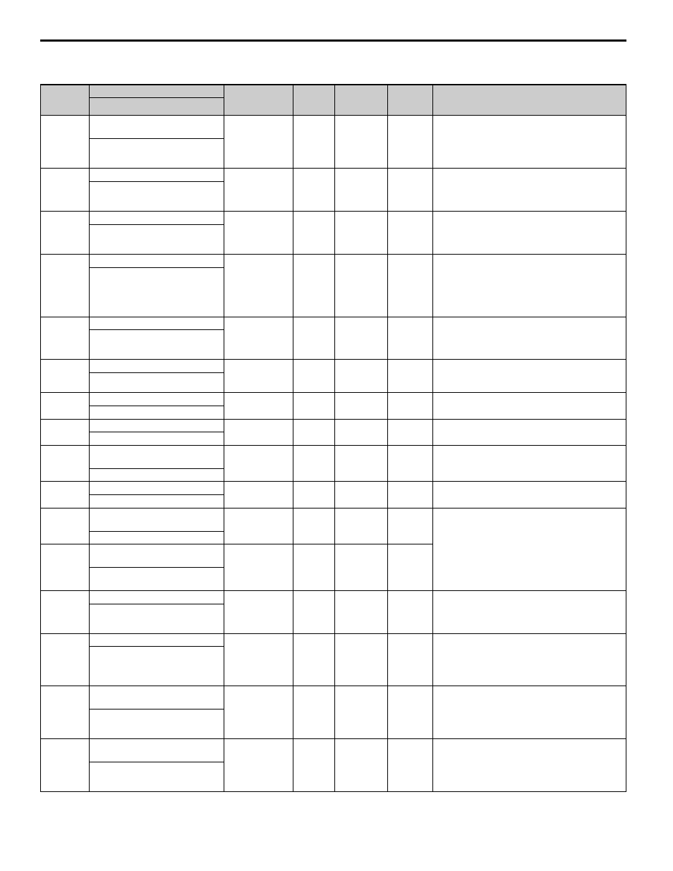
Table A.2 Parameter List
Parameter
No.
Parameter Name
Setting Range
Factory
Setting
Change
during
Operation
Access
Level
Description
Display
A1-00
Language selection for operator
display
0, 1
0
O
A
Language selection for the Digital Operator.
This parameter is not reset to the factory setting by
A1-03.
0: English
1: Japanese
[Select Language]
A1-01
Parameter access level
0 to 9999
4
O
A
Selects which parameters are accessible via the
Digital Operator.
0: Operation only
4: Advanced Level
[Access Level]
A1-03
Initialize
0000 to 9999
0000
x
A
Used to return all parameters to their factory or user
default settings. (Initializes and then returns A1-03 to
zero.)
2220: 2-Wire Initialization
[Init Parameters]
A1-04
Password 1 (Input)
0000 to 9999
0
x
A
When the value set into A1-04 does NOT match the
value set into A1-05, parameters A1-01 thru A1-03
cannot be changed. All other parameters as
determined by A1-01 can be changed. Parameter A1-
05 can be accessed by pressing the MENU key while
holding the RESET key.
[Enter Password]
b1-02
Operation method selection
0, 1
1
x
A
Selects the run command input source.
0: Operator- RUN and STOP keys on Digital
Operator.
1: Terminals - Contact closure on terminals S1 or S2.
[Run Source]
b1-06
Read sequence input twice
0, 1
1
x
A
Sets the scan rate of terminals S1 to S4
0: 500 ms - 2 scans (for quick response)
1: 5 ms - 2 scans (for noisy environments)
[Cntl Input Scans]
C8-17
Automatic operation stop current
10 to 100%
50
x
A
—
[Autorun Iout]
C8-18
Bias voltage at operation start
0.0 to 50.0 V
2.0
x
A
For 400 V class power regenerative units, double the
initial setting and setting range.
[V Bias of Run]
C8-19
Hysteresis voltage width at
operation start/stop
0.5 to 50.0 V
3.0
x
A
For 400 V class power regenerative units, double the
initial setting and setting range.
[V Width of Stop]
C8-20
Min. operating time
0.0 to 600.0 sec
1.0
x
A
—
[Minimum Run Time]
F1-10
Excessive frequency deviation
detection level
1.0 to 10.0 Hz
3.0
x
A
Configures the frequency deviation fault (DEV)
detection. DEV fault will occur if the frequency
deviation is greater than the F1-10 setting for a time
longer than F1-11. F1-10 is set as a percentage of the
maximum output frequency (E1-04). Frequency
deviation is the difference between actual input
supply frequency and the frequency reference
command.
[FDEV DetectLevel]
F1-11
Excessive frequency deviation
detection delay time
0.0 to 255.0 sec
70.0
x
A
[FDEV Detect Time]
H1-01
Multi-function input (terminal S3)
0 to 2F
24
O
A
Selects the function of terminal S3.
24: External fault, Normally Open, Always Detected,
Coast To Stop.
Refer to
[Terminal S3 Sel]
H1-02
Multi-function input (terminal S4)
0 to 2F
14
O
A
Selects the function of terminal S4.
14: Fault reset
Closed = Resets the Drive after the fault and the run
command have been removed.
Refer to
[Terminal S4 Sel]
H2-02
Multi-function output (terminal M1-
M2)
0 to 20
6
O
A
Selects the function of terminals M1 to M2.
6: Drive ready
Closed - When the Drive is powered up, not in a fault
state and in the DRIVE mode.
Refer to
[Terminal M1 Sel]
H2-03
Multi-function output (terminal M3-
M4)
0 to 20
0
O
A
Selects the function of terminals M2 - M4.
0: During Run 1
Closed - When a run command is input or the Drive
is outputting voltage.
Refer to
[Terminal M3 Sel]